Radiation Refrigeration Particle and Vapor Condensation Recovery Unit

A technology of radiation refrigeration and recovery device, used in refrigeration and liquefaction, steam/vapor condensers, refrigerators, etc., can solve the problems of adsorbent harmful to human body and the environment, consume large electric energy, and high requirements for adsorbent efficiency, and achieve condensation efficiency. good effect, promoting vapor condensation and good heat transfer performance

Active Publication Date: 2020-07-14
ZHEJIANG UNIV
View PDF13 Cites 0 Cited by
  • Summary
  • Abstract
  • Description
  • Claims
  • Application Information

AI Technical Summary

Problems solved by technology

[0005] The electric condensation method needs to consume a large amount of electric energy to take away the heat of the steam, while the adsorbent adsorption method requires high efficiency of the adsorbent, and the adsorbent is harmful to the human body and the environment

Method used


Image

  • Radiation Refrigeration Particle and Vapor Condensation Recovery Unit
  • Radiation Refrigeration Particle and Vapor Condensation Recovery Unit
  • Radiation Refrigeration Particle and Vapor Condensation Recovery Unit

Examples


Embodiment approach 1

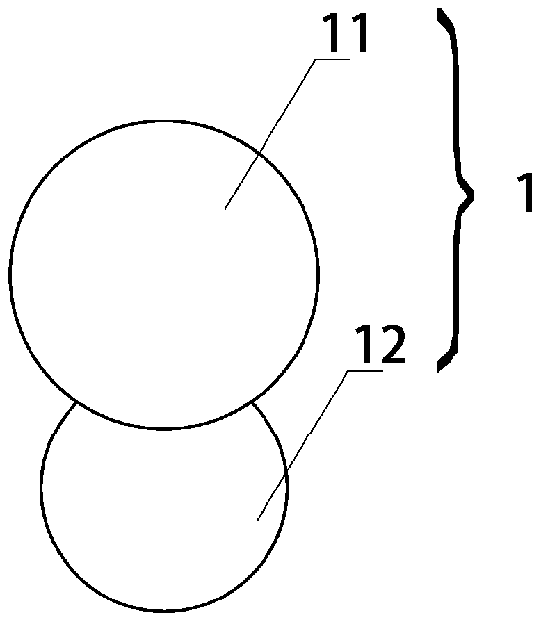
[0048] The first embodiment of the present invention provides a radiant cooling particle 1, see figure 1 As shown, it includes: condensate liquid 11, which is made of radiation refrigeration material;

[0049] The hydrophobic liquid 12 is connected with the condensate liquid 11 and is made of a liquid-repellent material;

[0050] When in use, the radiation cooling particles 1 are suspended in the medium under the blowing of the medium, and are used to condense the vapor in the medium.

[0051] Among them, the radiation cooling material is a material that can use infrared radiation to transfer heat from a heat source to a cold source in outer space through an atmospheric window of infrared radiation. Its refrigeration principle is similar to the natural refrigeration principle of the earth.

[0052]Those of ordinary skill in the art know that the energy of 200 petawatts that the earth absorbs from the sun every day is finally sent to the space near absolute zero in the form o...

Embodiment approach 2

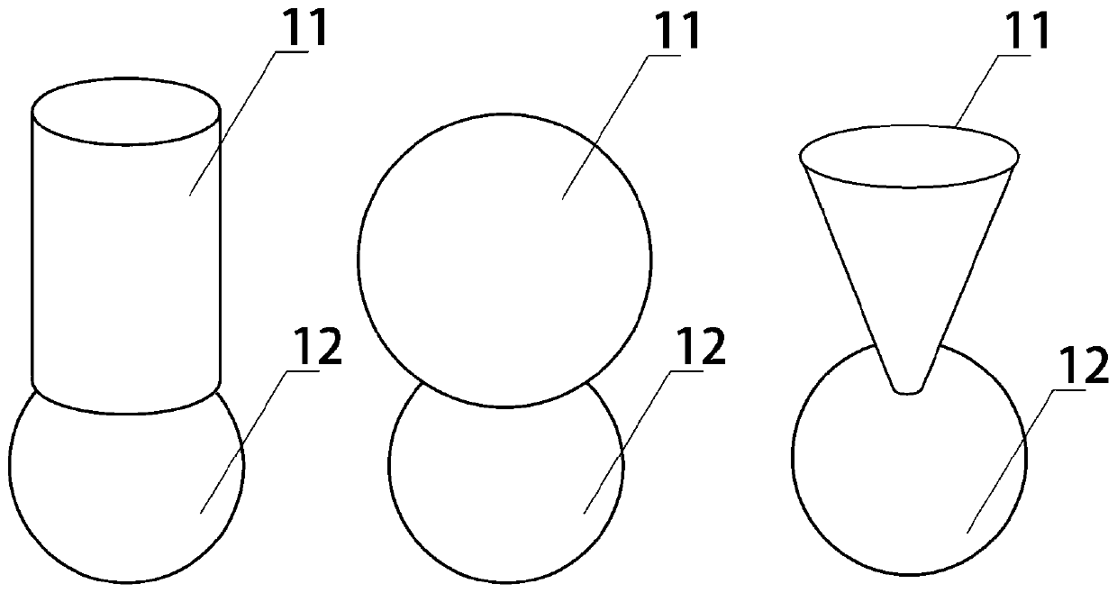
[0062] The second embodiment of the present invention provides a radiation cooling particle 1 . The second embodiment is a further improvement of the first embodiment, the main improvement is that, in the second embodiment of the present invention, see image 3 As shown, the condensate 11 is in the shape of a film, a thin shell or a flat plate.

[0063] Among them, see Figure 3a As shown, the film shape refers to the shape of a flexible film formed with a curved surface, its thickness is thin, and its length and width are relatively large relative to the thickness, which may deform due to force.

[0064] see Figure 3b As shown, the shell shape refers to the shape of a rigid shell formed with a curved surface, which can be compared to the shape of a part of an egg shell.

[0065] see Figure 3c As shown, the flat plate shape refers to a shape in which both sides are flat, the thickness is smaller than the length and width, and the material is rigid.

[0066] Those of ord...

Embodiment approach 3

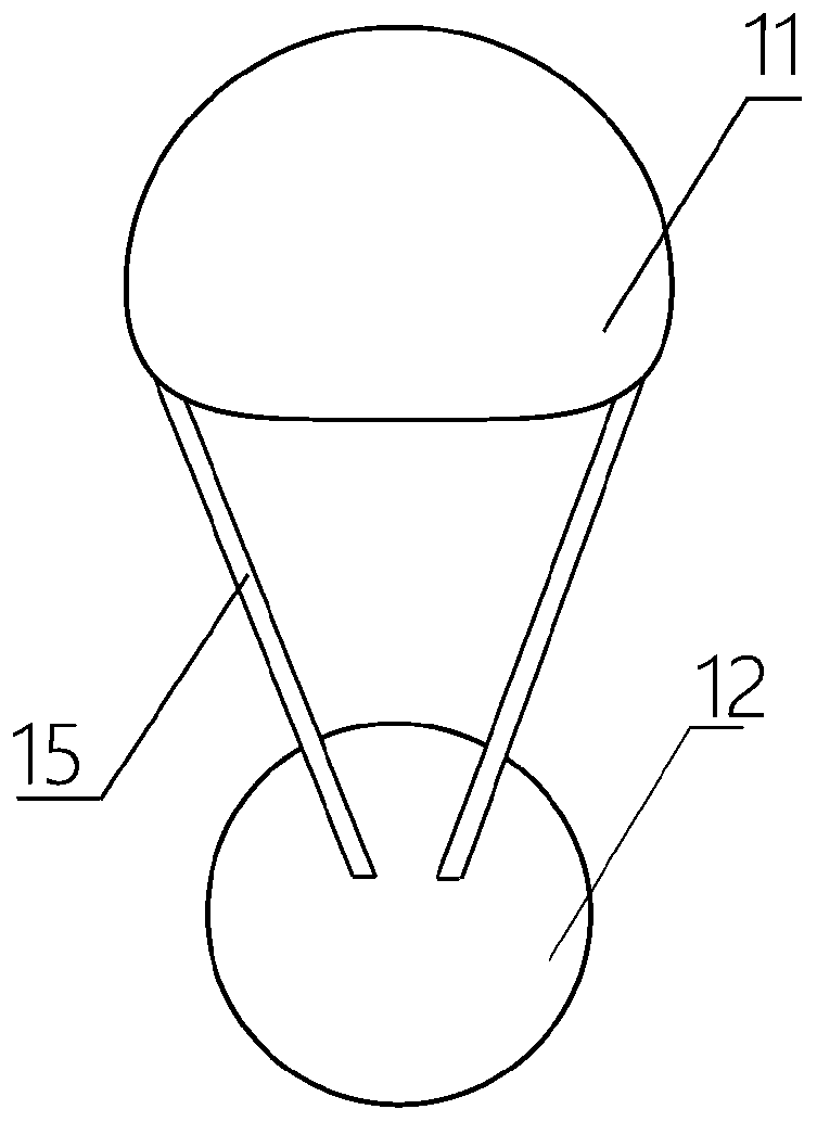
[0070] The third embodiment of the present invention provides a radiation cooling particle 1 . The third embodiment is a further improvement of the second embodiment, the main improvement is that, in the third embodiment of the present invention, see Figure 4 As shown, the hydrophobic liquid 12 is connected with the condensate liquid 11 through a thread 13 .

[0071] The condensate liquid 11 and the repellent liquid 12 are connected by wires 13 . Compared with the connection of the two by connecting rods 15 , the wires 13 are lighter and have almost no influence on the overall buoyancy of the radiative cooling particles 1 . Furthermore, under the action of gravity, the condensed liquid may carry the radiant cooling particles 1 and fall to the bottom of the vapor condensation chamber 2, and the liquid is detached from the surface of the radiative cooling particles 1 under the impact, and the wires 13 are less likely to be impacted. And detach from the radiation cooling partic...


PUM


Abstract

The invention relates to the field of steam recovery and discloses a radiation refrigeration particle and a steam condensation recovering device. The steam condensation recovering device comprises a steam condensation cavity and the radiation refrigeration particle, wherein the radiation refrigeration particle comprises a condensing body made of a radiation refrigeration material and a lyophobic body made of a lyophobic material, and the lyophobic body is connected with the condensing body. When used, the radiation refrigeration particle suspends in a medium under the blowing of the medium andis used for condensing steam in the medium. The radiation refrigeration particle can rapidly release latent heat of condensation to an external environment through radiation heat transferring under the situation that no extra energy is input and no adsorbent is used, and the steam is efficiently condensed.

Description

technical field [0001] The invention relates to the field of steam recovery, in particular to a radiation refrigeration particle and steam condensation recovery device. Background technique [0002] Most of my country's new coal-fired units are built in the western coal-producing areas, and these areas are water-scarce areas. How to build large-scale coal power bases in water-scarce areas is a thorny issue for energy workers. The newly-built units of coal-fired power plants in my country's water-scarce areas have actively installed air-cooled condensers, which has greatly reduced the water consumption of the power plants. However, the steam emitted by a 600MW unit through the chimney is about 300t / h, and the annual water discharge is about 1.5 million tons. The water consumption is still very alarming. If the water in the chimney can be recovered and utilized as a resource, it will strongly support the construction of my country's coal power base, and it will be of great si...

Claims


Application Information

Patent Timeline
Patent Type & Authority Patents(China)
IPC IPC(8): F25B23/00F28B9/08
CPCF25B23/003F28B9/08
Inventor 肖刚刘焕磊倪明江骆仲泱高翔程乐鸣岑可法
Owner ZHEJIANG UNIV
Why Eureka
Try Eureka