Circuit device of reducing energy consumption of sensor

A circuit device and sensor technology, which is applied in the direction of instruments, adjusting electric variables, control/regulation systems, etc., can solve the problems of high energy consumption of sensors, high energy consumption, and unfavorable battery life.

Inactive Publication Date: 2015-07-01
NINGBO SHUANGLIN AUTO PARTS
View PDF5 Cites 14 Cited by
  • Summary
  • Abstract
  • Description
  • Claims
  • Application Information

AI Technical Summary

Problems solved by technology

[0002] In an automatic control system, a sensor is usually used to detect the state of the controlled object. The sensor converts the detected physical quantity into an electrical signal and feeds it back to the MCU (microprocessor), and the MCU performs data processing on the feedback signal, including ADC conversion and discrimination. Output Control instructions, the control instructions control the controlled object through the executive agency; the work of the automatic control system is divided into working periods and standby periods, and the automatic control system of the equipment powered by AC power supplies continuous power regardless of the working period and standby period. Energy consumption; for equipment powered by batteries, such as automobiles, in order to reduce energy consumption and improve battery life, the automatic control system is in a dormant state during the standby period, and is awakened when processing is required; the vehicle-mounted automatic control system generally It needs to be woken up by a switch or a sensor, which prevents the sensor from sleeping; and the sensor requires a large working current. Even if the automatic control system sleeps, the energy consumption of the automatic control system is still very large, which is not conducive to extending the battery life.
For this reason, how to reduce the working energy consumption of the sensor has become the key to improving the endurance of the battery-powered system; Temperature sensors for oil temperature, water temperature, cabin air temperature, and engine body temperature. Many physical quantities change slowly and do not require sensors to continuously work and sample. It is only necessary to intermittently supply power to the sensors in different periods of time to start sampling; if these sensors do not need to work Sleep when needed, and wake up when it needs to work, so that the actual power consumption of these sensors can be reduced; however, in the prior art, there is no specific device for the intermittent operation of the sensor, so the existing technology has the problem of high energy consumption of the sensor. Problems and deficiencies

Method used


Image

  • Circuit device of reducing energy consumption of sensor
  • Circuit device of reducing energy consumption of sensor
  • Circuit device of reducing energy consumption of sensor

Examples


Embodiment 1

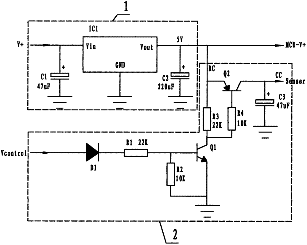
[0018] Embodiment 1, refer to figure 1 , a circuit device for reducing sensor energy consumption according to the present invention includes a voltage stabilizing circuit 1 and a sensor supply circuit 2, wherein: the voltage stabilizing circuit 1 is composed of a power supply chip IC1, a first capacitor C1 and a second capacitor C2; The sensor supply circuit 2 is composed of a first transistor Q1, a second transistor Q2, a switching diode D1, a third capacitor C3, a first resistor R1, a second resistor R2, a third resistor R3, and a fourth resistor R4; The first transistor Q1 is an NPN transistor, and the second transistor Q2 is a PNP transistor;

[0019] The positive pole V+ of the battery is connected to the positive pole of the first capacitor C1 and the voltage input terminal Vin of the power chip IC1, and the voltage output terminal Vout of the power chip IC1 is connected to the positive pole of the second capacitor C2, the emitter pole of the second transistor Q2, and th...

Embodiment 2

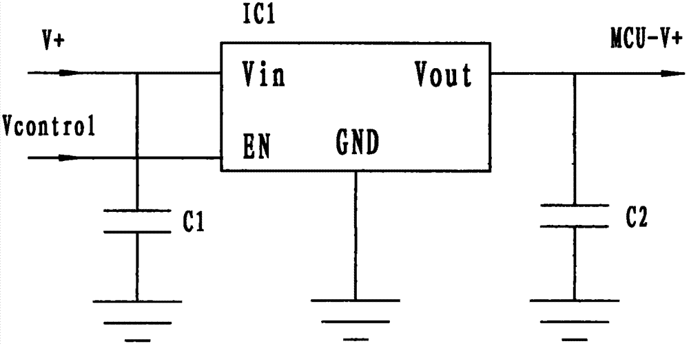
[0022] Embodiment 2, using a circuit composed of a power supply chip with an enable terminal EN, refer to figure 2 , the MCU provides the control voltage to the enabling terminal EN of the voltage stabilizing circuit, EN=1 is enabling, and EN=0 is disabling. When the control voltage is zero, the voltage regulator circuit has no voltage output, and the sensor has no current consumption. When the control voltage is at a high level, the regulated power supply outputs a voltage, and the sensor works. After the MCU turns on the sensor power supply for a proper delay, AD conversion can be performed to detect the corresponding output voltage of the sensor and detect the measured physical quantity.

[0023] There are two timers, A and B, in the MCU, and the A timer can work normally when the MCU sleeps and wakes up the MCU when the timing is over. After the MCU is woken up, first turn on the power supply of the sensor and start the B timer.

[0024] Sensors are divided into mathem...

Embodiment 3

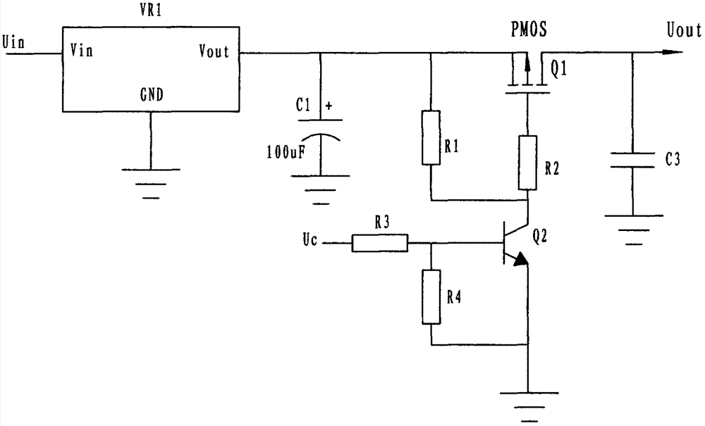
[0026] Embodiment 3, adopt PMOS tube to replace the circuit device of PNP transistor in embodiment 1, refer to image 3 , its working principle is similar to that of Example 1.

[0027] The comparison of embodiment 1 and embodiment 2:

[0028] The advantage of embodiment 1 is that the switching speed of the triode is very fast, there is basically no delay, and it can work in a narrower switching pulse state, which is suitable for occasions requiring fast response and has a wide range of applications; its weakness is that there are many components. The circuit is more complicated. In application, when the sensor and the MCU are powered by the same power supply, only the triode switch circuit of Embodiment 1 can be used, because the MCU cannot turn off the power supply.


PUM


Abstract

The invention discloses a circuit device of reducing the energy consumption of a sensor. The circuit device comprises a voltage stabilizing circuit (1) and a sensor power supply circuit (2), wherein the voltage stabilizing circuit consists of a power supply chip, a first capacitor and a second capacitor, and the sensor power supply circuit consists of a first transistor, a second transistor, a switching diode, a third capacitor, a first resistor, a second resistor, a third resistor and a fourth resistor; the voltage input end of the voltage stabilizing circuit is connected with the anode of a battery, the voltage output end of the voltage stabilizing circuit is connected with the anode of a microprocessor and the input end of the sensor power supply circuit, and the output end of the sensor power supply circuit is connected with the power end of a sensor; when the circuit device operates, the sensor power supply circuit is conducted to operate when the sensor power supply circuit is controlled by the microprocessor and an MCU (Microprogrammed Control Unit) control level end is a high level, and the sensor power circuit is closed and the sensor stops operating when the MCU control level end is a zero level; by adopting a technical scheme of reducing the total energy consumption of the sensor by controlling the intermittent service and dormancy of the controller.

Description

technical field [0001] The invention relates to a circuit device, in particular to a circuit device for reducing sensor power consumption in an automatic control system. Background technique [0002] In an automatic control system, a sensor is usually used to detect the state of the controlled object. The sensor converts the detected physical quantity into an electrical signal and feeds it back to the MCU (microprocessor), and the MCU performs data processing on the feedback signal, including ADC conversion and discrimination. Output Control instructions, the control instructions control the controlled object through the executive agency; the work of the automatic control system is divided into working periods and standby periods, and the automatic control system of the equipment powered by AC power supplies continuous power regardless of the working period and standby period. Energy consumption; for equipment powered by batteries, such as automobiles, in order to reduce ene...

Claims


Application Information

Patent Timeline
Patent Type & Authority Applications(China)
IPC IPC(8): G05F1/56
Inventor 杜林新张帅涛
Owner NINGBO SHUANGLIN AUTO PARTS
Why Eureka
Try Eureka