
Mask for calibration and method for calibration

A mask and shielding line technology, applied in the field of correction masks and corrections, can solve problems such as complicated operations and difficult actual measurement of angles

Inactive Publication Date: 2014-11-26
V TECH CO LTD
View PDF2 Cites 0 Cited by
  • Summary
  • Abstract
  • Description
  • Claims
  • Application Information

AI Technical Summary

Problems solved by technology

[0011] On the other hand, although the magnification of the laser lens of the line CCD camera can be confirmed in advance, it is difficult to actually measure the angle formed between the mask and the substrate and the line CCD camera, and it is necessary to confirm the line CCD in advance. The operation of the resolution of the camera requires a preparatory operation for setting the exposure mask and the substrate on the actual exposure device
However, since the substrate becomes larger, multiple exposure masks are arranged, and the line CCDs independently correspond to each exposure mask, so the above-mentioned operations are complicated.

Method used


Image

  • Mask for calibration and method for calibration
  • Mask for calibration and method for calibration
  • Mask for calibration and method for calibration

Examples


Embodiment Construction

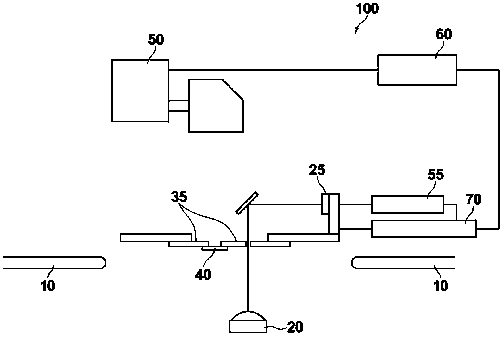
[0055] Refer below figure 1A calibration method for measuring the resolution of an image sensor for a calibration mask according to an embodiment of the present invention and an exposure device using the calibration mask.

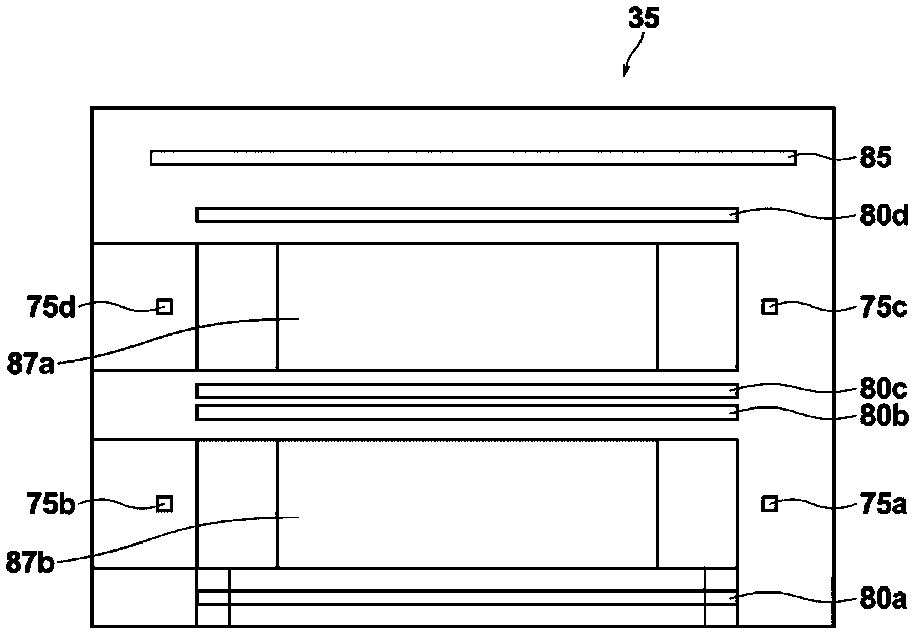
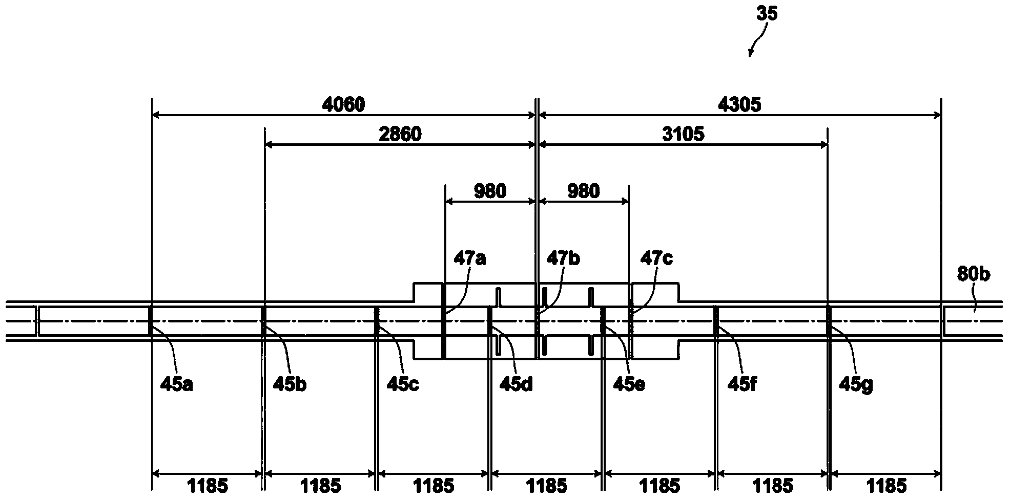
[0056] figure 2 It is a configuration diagram showing a correction mask portion 35 according to an embodiment of the present invention. The mask portion 35 has alignment marks 75a to 75d, image acquisition windows (line CCD observation windows) 80a to 80d, a mask ID 85, exposure windows 87a and 87b, and is arranged on the lower side of the image acquisition window 80 in a pasted manner as follows: Figure 4 The glass face 40 is shown. Such as Figure 5 As shown, the mask portion 35 is bonded to the glass portion 40 via an adhesive layer 49 . The glass surface portion 40 is located on the substrate side of the mask portion 35 and is made of a glass material adhered to the lower side near the image acquisition window 80 using an adhesive layer. The hei...


PUM


Abstract

The present invention can easily measure the resolution of an image sensor for adjusting and exposure position in an exposure device. A mask for calibration is provided with: a mask part provided with an image acquisition window for acquiring an image; a glass surface part that is on the lower side of the mask part and is constituted of a glass material attached in the vicinity of the image acquisition window using an adhesive layer; and shielding wire groups for which shielding wires constituted of a shielding material are provided on each of the image acquisition window and glass surface part. Light passing through the mask for calibration excluding the shielding wire groups is received, the light that has been received is converted into image information from the top, and the resolution information is measured on the basis of the image information.

Description

technical field [0001] The present invention relates to a calibration mask and a calibration method, and more particularly to a calibration mask and a calibration method for measuring the resolution of an image sensor used for exposure position control of an exposure device. Background technique [0002] In the prior art, there is known an exposure apparatus for a substrate such as a color filter of a liquid crystal display device, in which the substrate and the mask are moved in a certain direction relative to each other while the exposure mask is brought close to the substrate. , while using the exposure position adjustment unit to adjust the exposure position of the substrate and the exposure mask in a direction at right angles to the moving direction, and irradiate the exposure light to the exposure mask to transfer and expose the exposure pattern on the substrate. The exposure mask has an exposure pattern for accurately exposing the above-mentioned substrate. [0003] ...

Claims


Application Information

Patent Timeline
Patent Type & Authority Applications(China)
IPC IPC(8): G03F9/00G03F1/00
CPCG03F9/7088G03F1/42G03F9/7019
Inventor 野村义昭松本隆德竹下琢郎
Owner V TECH CO LTD
Learn More