
Mosaic quantification by birefringence measurement

a birefringence and crystal structure technology, applied in the measurement of optical radiation, instruments, light polarisation, etc., can solve the problems of crystal structure, affecting the long-range cell order is a grain boundary, and degrading the performance of crystal optical materials, and achieve high accuracy

Inactive Publication Date: 2008-05-29
CORNING INC
View PDF2 Cites 0 Cited by
  • Summary
  • Abstract
  • Description
  • Claims
  • Application Information

AI Technical Summary

Benefits of technology

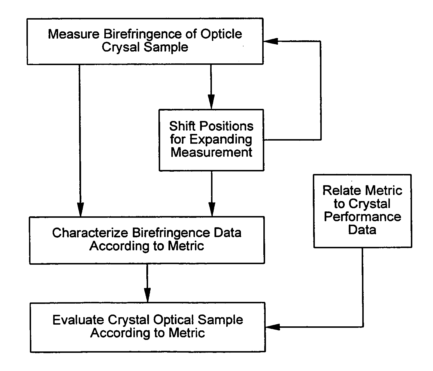
[0016]The invention involves a new approach to mosaic quantification, which is intended to overcome certain of the drawbacks of the prior art by preserving crystal sample integrity, providing timely measurement results, and avoiding the need for specialized equipment with limited availability. In one or more preferred embodiments, a high spatially resolved birefringence measurement is made having a spatial resolution fine enough to resolve the stress created at the sub-grain boundaries. The birefringence measurements can be made using optically transmissive wavelengths. Because the birefringence is measured at such a fine scale and with optically transmissive wavelengths, mosaic level can be quantified to high accuracy without inflicting damage to the crystal sample.

Problems solved by technology

In actual crystals, defects interrupt the periodic order of crystal structures, which can degrade the performance of crystal optical materials.
A major defect that affects the long-range cell order is a grain boundary.
Another recurring defect in crystal structure is a subgrain boundary.
In optical materials, high levels of mosaic are undesirable and thought to shorten the lifetime (e.g., service life) of crystal optical materials, particularly with respect to the transmission of shorter wavelengths in the deep ultraviolet spectrum.
However, each has drawbacks associated with measurement time, measurement equipment, material damage, or a lack of quantifiable results.
X-rays directed to the crystal surface constructively interfere with the crystal structure when the X-ray energy and lattice spacings and angles meet specific criteria.
However, such multiple exposures can take hours to complete per sample, and the X-rays expose the crystal to ionizing radiation that can damage the crystal material of the sample.
However, specialized equipment is required to carry out this method, which is available in only a few locations in the world.
In addition, the X-rays expose the crystal sample to damaging ionizing radiation.
Again, highly specialized equipment is needed, and the exposure of the crystal sample to ionizing radiation can cause damage.
However, the inspection is limited to the cleaved surface of the sample, the cleaving itself causes obvious damage, and the estimate of mosaic is highly subjective.
Mosaic, since it is disorder of the lattice, makes this color shift less uniform.
The method allows a quick mosaic evaluation, but is highly subjective and can only yield relative ratings of low, medium, and high.
Even these ratings can be questionable, since the amount of birefringence seen is affected by both the crystal orientation and the tested sample length.
A sample material with very low stress has low amounts of stress birefringence and therefore a low signal output, which makes estimates of mosaic more difficult.
Quantification, however, is problematic.
However, the method tends to be labor intensive and quite slow.

Method used


Image

  • Mosaic quantification by birefringence measurement
  • Mosaic quantification by birefringence measurement
  • Mosaic quantification by birefringence measurement

Examples


Embodiment Construction

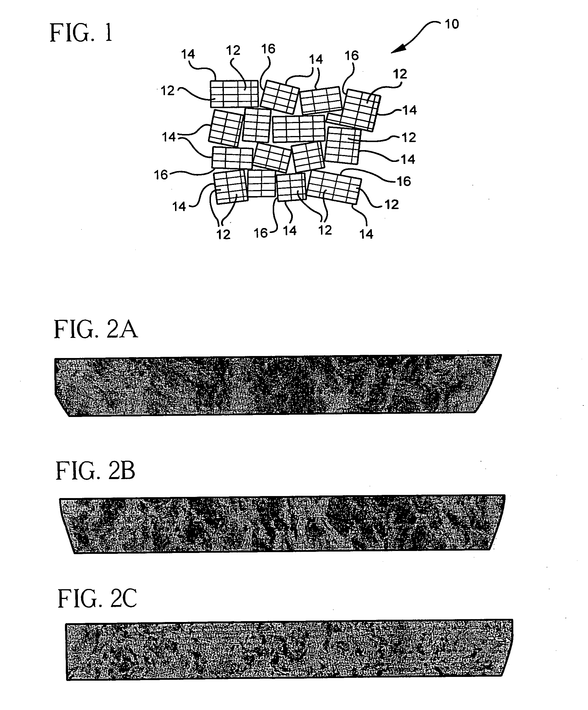
[0031]In a schematic representation of a mosaic structure of a single crystal grain 10 as shown in FIG. 1, dislocations between some of the unit cells 12 divide the crystal grain 10 into an assembly of subgrains 14 that slightly misalign groups of unit cells 12 with respect to one another. The misalignments shown in FIG. 1 are greatly exaggerated to distinguish boundaries 16 where the dislocations occur from regions within the subgrains 14 where the periodic crystal order among the unit cells 12 is maintained. The misaligned subgrains 14 resemble the tiles of a mosaic, and the arrangement of the subgrains 14 and particularly the network of their boundaries 16 are referred to as mosaic.

[0032]As a measure of local defects in the crystal structure, a high level of mosaic is generally undesirable for optically transmissive materials. For example, a relationship has been found between mosaic level and lifetime issues (e.g., the service life) of optical crystal samples as well as other is...


PUM

PropertyMeasurementUnit
wavelengthaaaaaaaaaa
latticeaaaaaaaaaa
birefringenceaaaaaaaaaa

Abstract

A crystal optical material is illuminated at a wavelength of light that does not ionize the crystal optical material. Birefringence is measured between a plurality of voxels within the crystal optical material having spatial dimensions small enough to distinguish optical propagations of the light encountering boundary regions between subgrains of the crystal mosaic from optical propagations of the light through the subgrains themselves. The measured birefringence is evaluated for quantifying a characteristic of the crystal matrix. Metrics describing the crystal matrix are associated with performance of the crystal optical material.

Description

FIELD OF THE INVENTION[0001]The invention relates to the measurement of crystal structures and, in particular, to the quantification of crystal mosaics by birefringence measurements.BACKGROUND OF THE INVENTION[0002]Some crystal materials can perform well as optical materials, particularly for transmitting shorter wavelengths of light such as ultraviolet or deep ultraviolet light where most amorphous optical materials are less transmissive or more susceptible to optical damage. However, the ordered structure of crystalline optical materials in the form of repeating cells of atoms or molecules arranged in lattice can have directionally dependent properties unlike amorphous materials like glass. For example, refractive index can be affected by the direction at which light encounters periodic crystal structures. Such directionally dependent refractive index properties are referred to as birefringence.[0003]Uniaxial crystal materials, such as calcium fluoride, which express three-dimensi...

Claims


Application Information

Patent Timeline
Patent Type & Authority Applications(United States)
IPC IPC(8): G01N21/23
CPCG01N21/23
Inventor ROSCH, WILLIAM ROGERSSCHREIBER, HORST
Owner CORNING INC
Learn More