Methods and devices for measuring orbital angular momentum states of electrons

a technology of orbital angular momentum and electrons, applied in the field of electron microscopy and spectroscopy, can solve the problems of fundamental differences and no equivalent technique for measuring the orbital angular momentum of photons

Active Publication Date: 2018-05-01
UNIVERSITY OF OREGON
View PDF3 Cites 4 Cited by
  • Summary
  • Abstract
  • Description
  • Claims
  • Application Information

AI Technical Summary

Benefits of technology

[0022]The measurement technique allows for dual measurement of the energy and orbital angular momentum distributions of inelastically scattered electrons, and therefore makes possible a wide range of new spectroscopy experiments. The highly anticipated application of electron vortex beams to atomic resolution magnetization measurement is technically easier with our measurement technique. Recently, theorists in ionization spectroscopy have noticed that ionized electrons can carry orbital angular momentum and that post-selection can reveal more about interactions with atoms. Electron orbital angular momentum is a useful degree of freedom for probing materials and basic atom and particle interactions, and our technique would enable these applications.

Problems solved by technology

However, fundamental differences arise when applying these principles to realize a practical device.
No equivalent technique yet exists for measurement of photon orbital angular momentum.

Method used


Image

  • Methods and devices for measuring orbital angular momentum states of electrons
  • Methods and devices for measuring orbital angular momentum states of electrons
  • Methods and devices for measuring orbital angular momentum states of electrons

Examples


Embodiment Construction

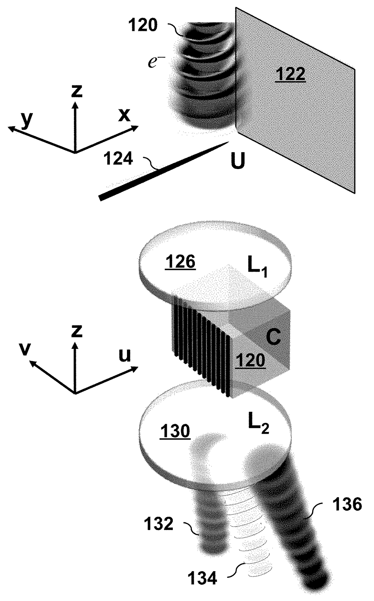
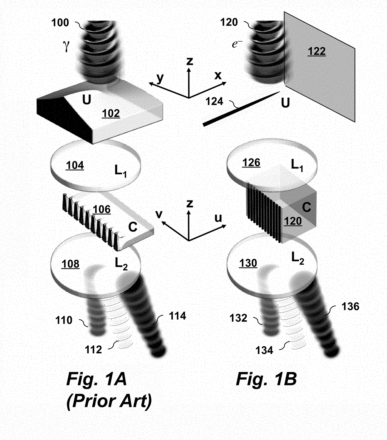
[0042]An embodiment of the invention is shown schematically in FIG. 1B.

[0043]An electron beam 120 with mixed OAM states is incident on the top of the device. A phase unwrapper element 122, 124 (U) in the front focal plane of a lens system 126 (L1) is followed by a phase corrector element 120 (C) in the back focal plane of lens system 126 (L1). For electrons, the element U is implemented using a conductive plate 122 and electrode 124. The electrode may be a charged needle or knife edge oriented axially to present a needle-like profile to the beam. The corrector element 120 (C) is an array of electrodes with alternating bias. Immediately after an electron beam passes through the corrector element C, its different OAM components are separated in momentum space. At the bottom of the device, a Fourier-transforming lens 130 (L2) separates OAM components into spatially separated beams in position space.

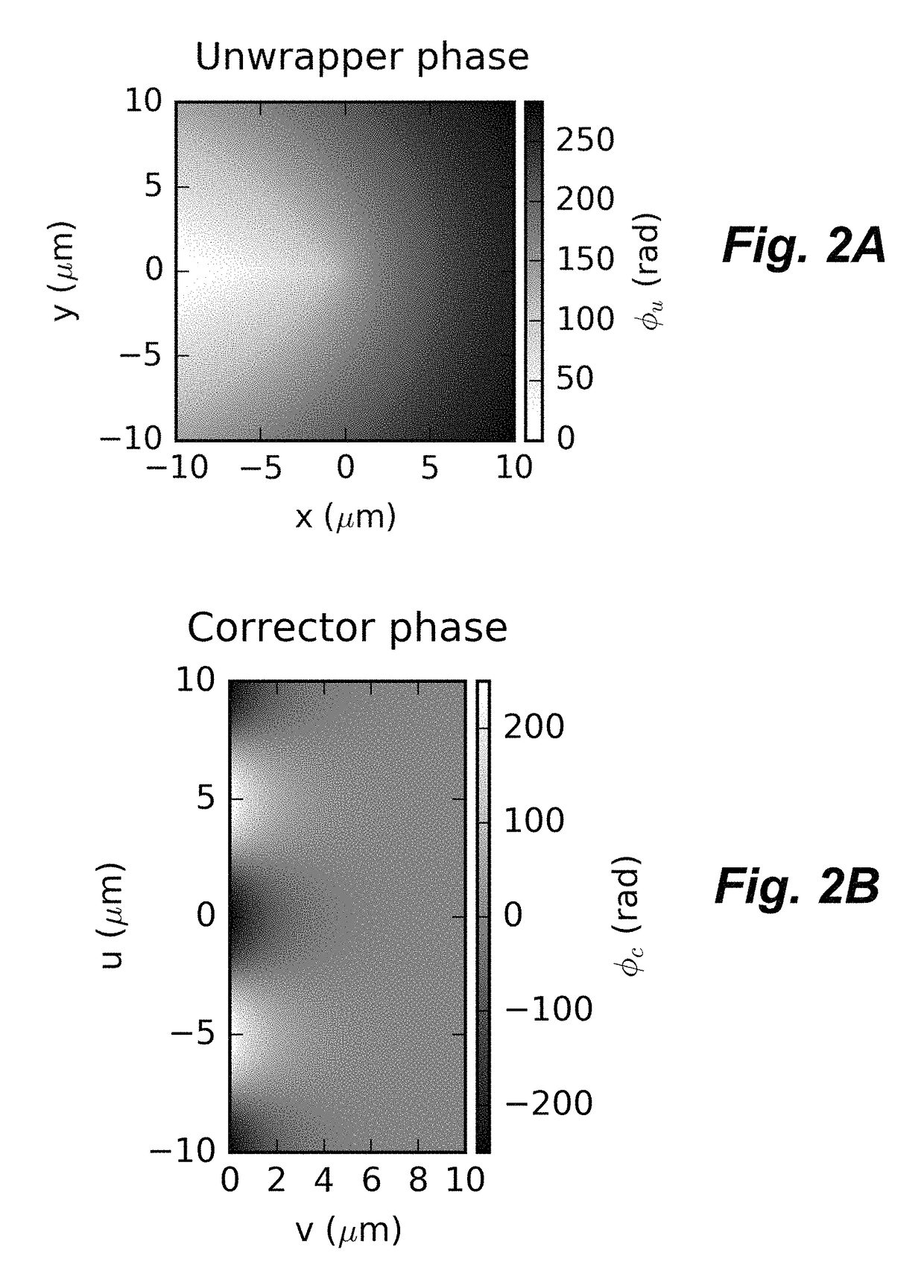
[0044]FIG. 2A is a graph of the phase profile of the unwrapper element U described in Eq...


PUM


Abstract

A device for measuring electron orbital angular momentum states in an electron microscope includes the following components aligned sequentially in the following order along an electron beam axis: a phase unwrapper (U) that is a first electrostatic refractive optical element comprising an electrode and a conductive plate, where the electrode is aligned perpendicular to the conductive plate; a first electron lens system (L1); a phase corrector (C) that is a second electrostatic refractive optical element comprising an array of electrodes with alternating electrostatic bias; and a second electron lens system (L2). The phase unwrapper may be a needle electrode or knife edge electrode.

Description

CROSS-REFERENCE TO RELATED APPLICATIONS[0001]This application claims priority from U.S. Provisional Patent Application 62 / 353,822 filed Jun. 23, 2016, which is incorporated herein by reference.STATEMENT REGARDING FEDERALLY SPONSORED RESEARCH OR DEVELOPMENT[0002]This invention was made with Government support under contract DE-SC0010466 awarded by the Department of Energy. The Government has certain rights in the invention.FIELD OF THE INVENTION[0003]The present invention relates generally to electron microscopy and spectroscopy. More specifically, it relates to techniques and devices for measuring orbital angular momentum states of electrons.BACKGROUND OF THE INVENTION[0004]Orbital angular momentum (OAM) is a recently discovered property of free electrons, also called electron vortices.[0005]Recent work has focused both on fundamental questions regarding electron vortex production, dynamics and properties. Work has also been done on techniques for preparing electron probe beams with...

Claims


Application Information

Patent Timeline
Patent Type & Authority Patents(United States)
IPC IPC(8): H01J37/12
CPCH01J37/12H01J37/244H01J37/26H01J2237/24514
Inventor MCMORRAN, BENJAMIN J.HARVEY, TYLER R.
Owner UNIVERSITY OF OREGON
Why Eureka
Try Eureka