
Laser-based measuring apparatus for measuring an axial run-out in a cylinder of rotation and method for measuring the same utilizing opposing incident measuring light beams

a technology of axial run-out and measuring apparatus, which is applied in the direction of measuring devices, instruments, electromagnetic wave reradiation, etc., can solve the problems of optical interference between light beams and inability to use interferometers, and achieve the effect of increasing the measuring resolution twice as high

Inactive Publication Date: 2005-10-11
PIONEER CORP
View PDF7 Cites 2 Cited by
  • Summary
  • Abstract
  • Description
  • Claims
  • Application Information

AI Technical Summary

Benefits of technology

[0016]The present invention has been made in view of the foregoing circumstance, and it is an object of the invention to provide a laser measuring apparatus and method which are capable of optically doubling the measurement resolution in a simple optical configuration, irrespective of which types of interferometer and reflector are used.
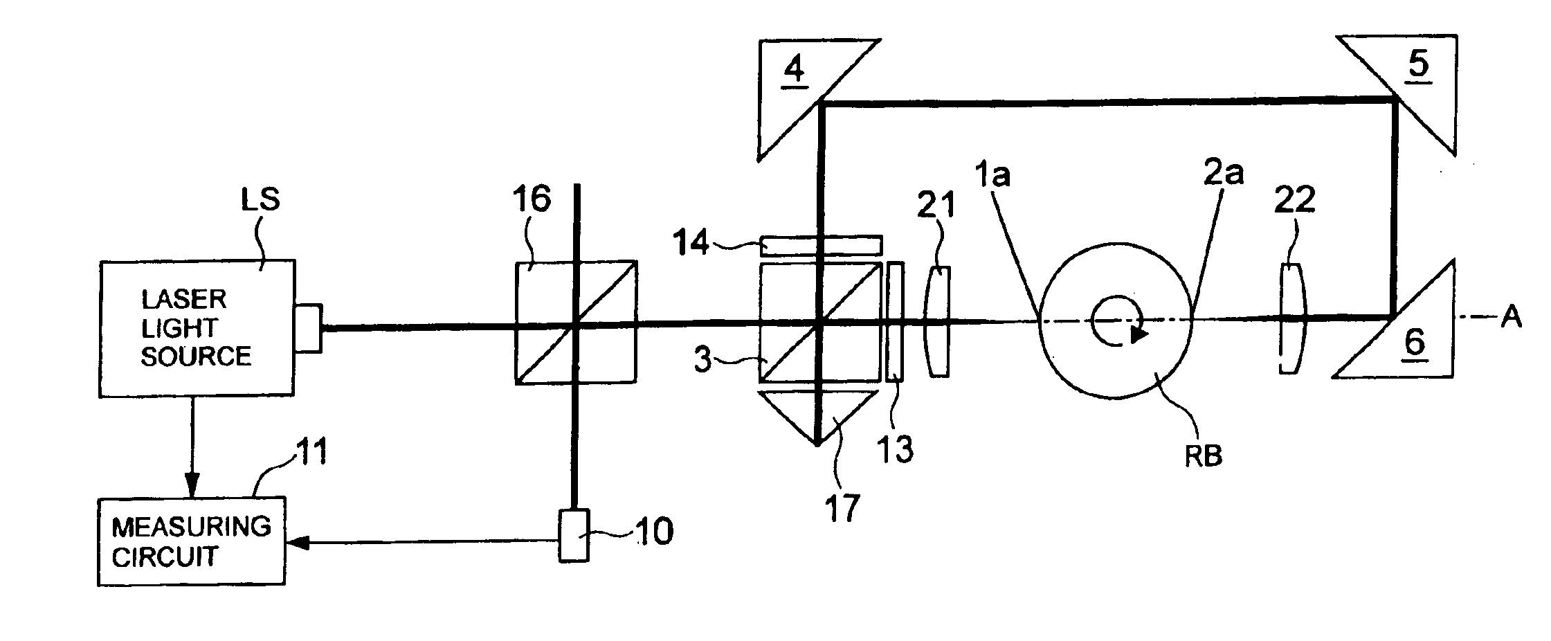
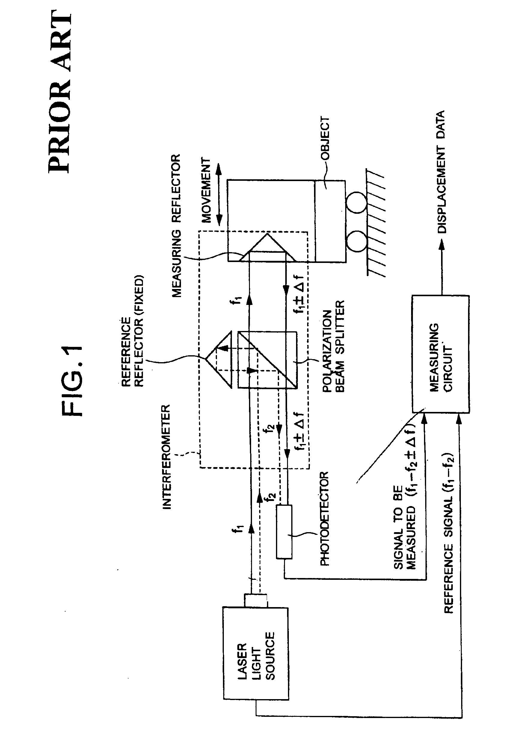
[0031]The displacement of object's movement is measured by the interference of light reflected by the fixed reference reflector with light reflected by the movable measuring reflector mounted on the moving object in the conventional laser-based measuring apparatus. In contrast, according to the invention, the laser-based measuring apparatus eliminates a fixed reference reflector, and arranges two reflectors or reflection planes in a back-to-back relationship to each other on a measuring axis of a moving object, such that the measuring apparatus directs two light beams split by a polarization beam splitter of an interferometer into the two reflectors from opposite directions, and differentially measures a relative displacement from the polarization beam splitter to the back-to-back arranged reflector pair to double a detected displacement, thereby making it possible to increase the measuring resolution twice as high as the conventional configuration.

Problems solved by technology

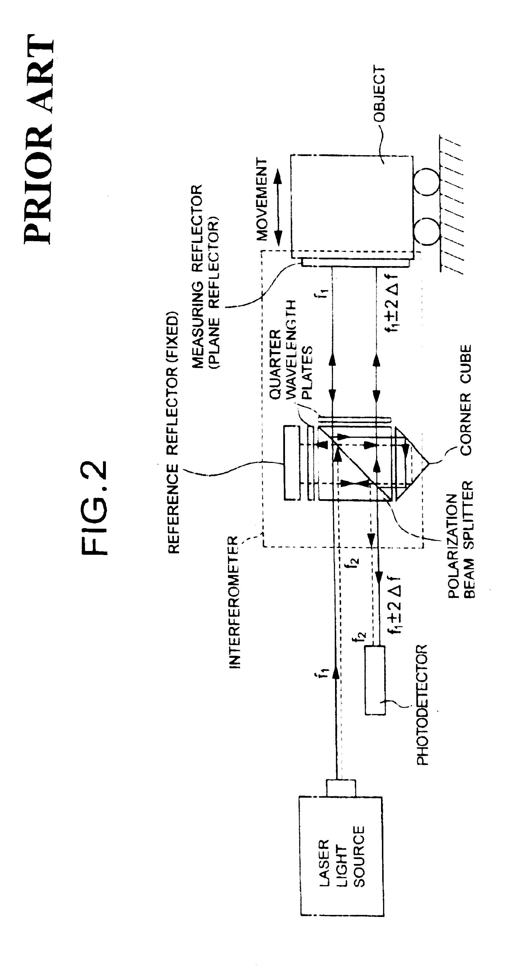
The interferometer divides light from a laser light source into at least two coherent light beams, passes the divided light beams through different optical paths from each other, and makes the resultant light beams optically interfere with each other after recombination.
Therefore, these interferometers cannot be used when a small measuring reflective plane is measured due to a limited space, or when a measuring reflective plane is not plane, such as cylindrical, spherical and the like.

Method used


Image

  • Laser-based measuring apparatus for measuring an axial run-out in a cylinder of rotation and method for measuring the same utilizing opposing incident measuring light beams
  • Laser-based measuring apparatus for measuring an axial run-out in a cylinder of rotation and method for measuring the same utilizing opposing incident measuring light beams
  • Laser-based measuring apparatus for measuring an axial run-out in a cylinder of rotation and method for measuring the same utilizing opposing incident measuring light beams

Examples


Embodiment Construction

[0035]In the following, a laser-based measuring apparatus according to one embodiment of the present invention will be described with reference to the drawings.

[0036]FIG. 3 illustrates the configuration of a linear interferometer to which a differential measurement is applied in accordance with the laser-based measuring apparatus of the embodiment. The laser-based measuring apparatus comprises a linear interferometer and a laser light source LS e.g., He—Ne laser. The linear interferometer comprises a polarization beam splitter 3; an optical system made up of two reflectors 1, 2 positioned on a measuring axis A of an object B in a back-to-back relationship to each other; and beam benders (45-degree reflectors) 4, 5, 6 which are positioned such that two light beams f1, f2 separated by the polarization beam splitter 3 are incident on the two reflectors 1, 2 from opposite directions to each other. The two light beams f1, f2 from the laser light source LS having different frequency compo...


PUM


Abstract

A laser-based measuring apparatus divides a light beam from a laser light source into at least two light beams, passes the light beams through different optical paths from each other, recombines the light beams, has the light beams interfere with each other to generate interfered light, opto-electrically transduces the interfered light to an optical frequency, and measures the amount of travel of an object which changes an optical path length of a portion of an optical path based on the optical frequency. The measuring apparatus has a portion for generating at least two measuring light beams from the laser light source, two reflection planes included in an object moving on a measuring axis, arranged back-to-back to each other on the measuring axis, and an opposing incident optical system for directing the measuring light beams into the reflection planes, respectively, such that the measuring light beams oppose to each other on the measuring axis.

Description

BACKGROUND OF THE INVENTION[0001]1. Field of the Invention[0002]The present invention relates to a laser-based measuring apparatus and a method for measuring the length or distance of an object under measurement.[0003]2. Description of the Related Art[0004]An interferometer has been applied in measuring technology. The interferometer divides light from a laser light source into at least two coherent light beams, passes the divided light beams through different optical paths from each other, and makes the resultant light beams optically interfere with each other after recombination.[0005]Measurements of length utilizing light waves are classified into a coincidence method which observes interference fringes at both ends of an object under measurement to measure the length of the object, and a counting method which employs an interferometer having a movable measuring reflector which is moved from a start point to an end point of a length under measurement to count bright and dark regi...

Claims


Application Information

Patent Timeline
IPC IPC(8): G01B9/02G01B11/00G01S7/48G01S17/88
CPCG01B9/02045G01B9/02007G01B9/02003G01B9/02021G01B2290/70
Inventor KITAHARA, HIROAKIKOJIMA, YOSHIAKIWADA, YASUMITSU
Owner PIONEER CORP
Learn More