
X-ray diffraction apparatus and method of measuring X-ray diffraction

a technology of x-ray diffraction and diffraction apparatus, which is applied in the direction of instruments, measurement devices, scientific instruments, etc., can solve the problems of increasing the cost of x-ray diffraction apparatus, and taking time and labor to change the measurement resolution by slit exchang

Active Publication Date: 2016-04-26
RIGAKU CORP
View PDF4 Cites 0 Cited by
  • Summary
  • Abstract
  • Description
  • Claims
  • Application Information

AI Technical Summary

Benefits of technology

The present invention allows for changing the measurement resolution without using a rear optical receiving slit. This flexibility helps to overcome any limitations that might occur when using the rear optical receiving slit.

Problems solved by technology

Therefore, there is a problem that it takes time and labor to change the measurement resolution by slit exchange.
However, since the opening / closing mechanism of the slit is expensive compared to the type of exchanging the slit by the manual insertion method, there is a problem that it causes cost increase of the X-ray diffraction apparatus.
Also, when disposing a monochromator crystal or an analyzer crystal in an optical path of the X-rays from the sample S on the sample stage 7 to the detector 13 to detect the X-rays by a higher measurement resolution, the cost is increased further.
However, in that case, before and after installing the monochromator crystals 14a and 14b, a position of the X-rays incident on the detection surface of the detector 13 is shifted by L. Therefore, in the type including the opening / closing mechanism of the slit, a moving mechanism is separately required for shifting an opening / closing center position of the rear optical receiving slit 11 by mechanically moving a slit position of the rear optical receiving slit 11 according to a shift amount L of the incident position of the X-rays, thus resulting in a further cost increase.

Method used


Image

  • X-ray diffraction apparatus and method of measuring X-ray diffraction
  • X-ray diffraction apparatus and method of measuring X-ray diffraction
  • X-ray diffraction apparatus and method of measuring X-ray diffraction

Examples


Embodiment Construction

[0076]Hereinafter, an embodiment of the present invention will be described in detail with reference to the drawings.

[0077]In the embodiment of the present invention, descriptions will be given in the following order.

[0078]1. Measurement optical system of X-ray diffraction apparatus

[0079]2. First constitutional example of X-ray diffraction apparatus

[0080]3. Method of measuring X-ray diffraction

[0081]4. First example of setting screen of virtual mask

[0082]5. Relationship between opening condition of virtual mask and signal processing

[0083]6. Second example of setting screen of virtual mask

[0084]7. Second constitutional example of X-ray diffraction apparatus

[0085]8. Effects of embodiment

[0086]9. Modifications or the like

1. Measurement Optical System of X-Ray Diffraction Apparatus

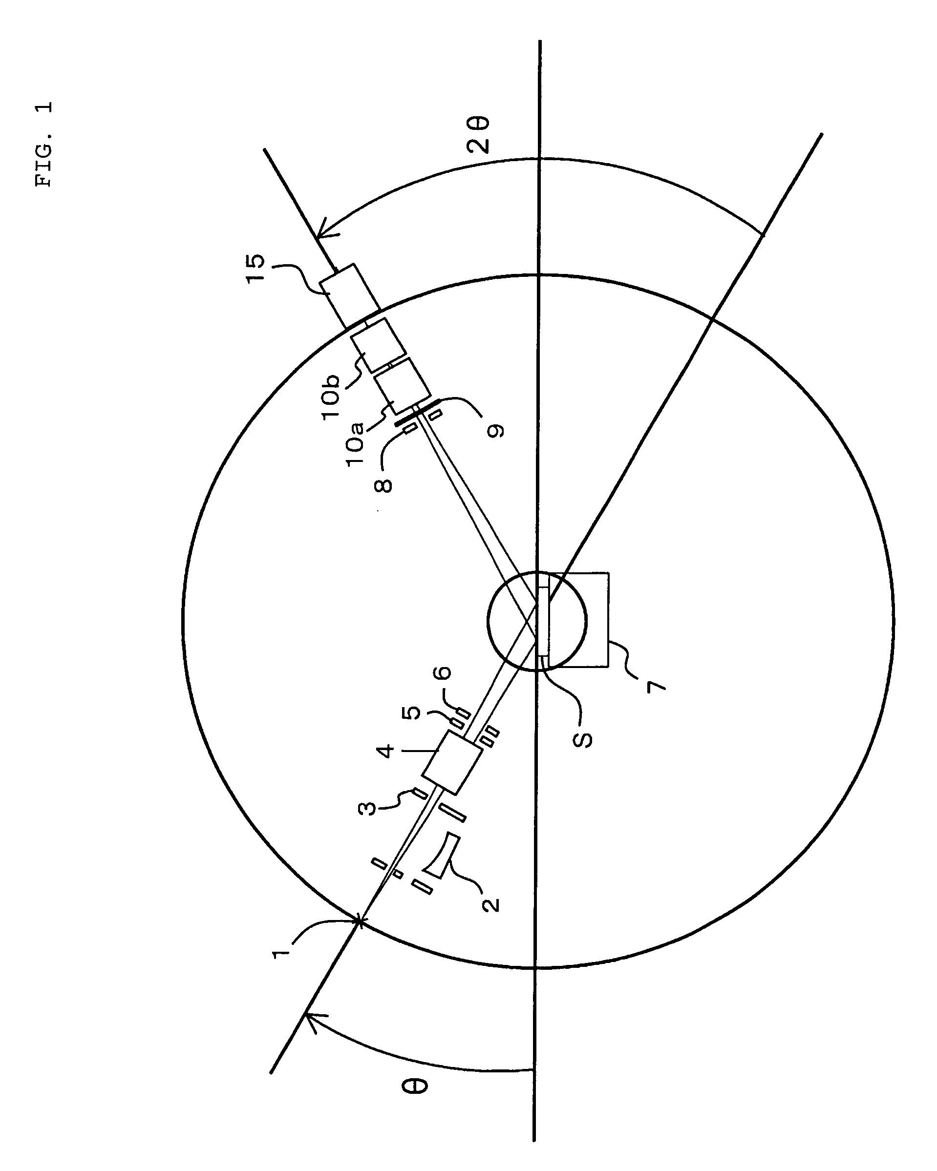
[0087]FIG. 1 is a schematic diagram illustrating a constitutional example of a measurement optical system of an X-ray diffraction apparatus according to an embodiment of the present invention.

[0088]In FIG. 1, ...


PUM

PropertyMeasurementUnit
widthaaaaaaaaaa
widthaaaaaaaaaa
inclination angleaaaaaaaaaa

Abstract

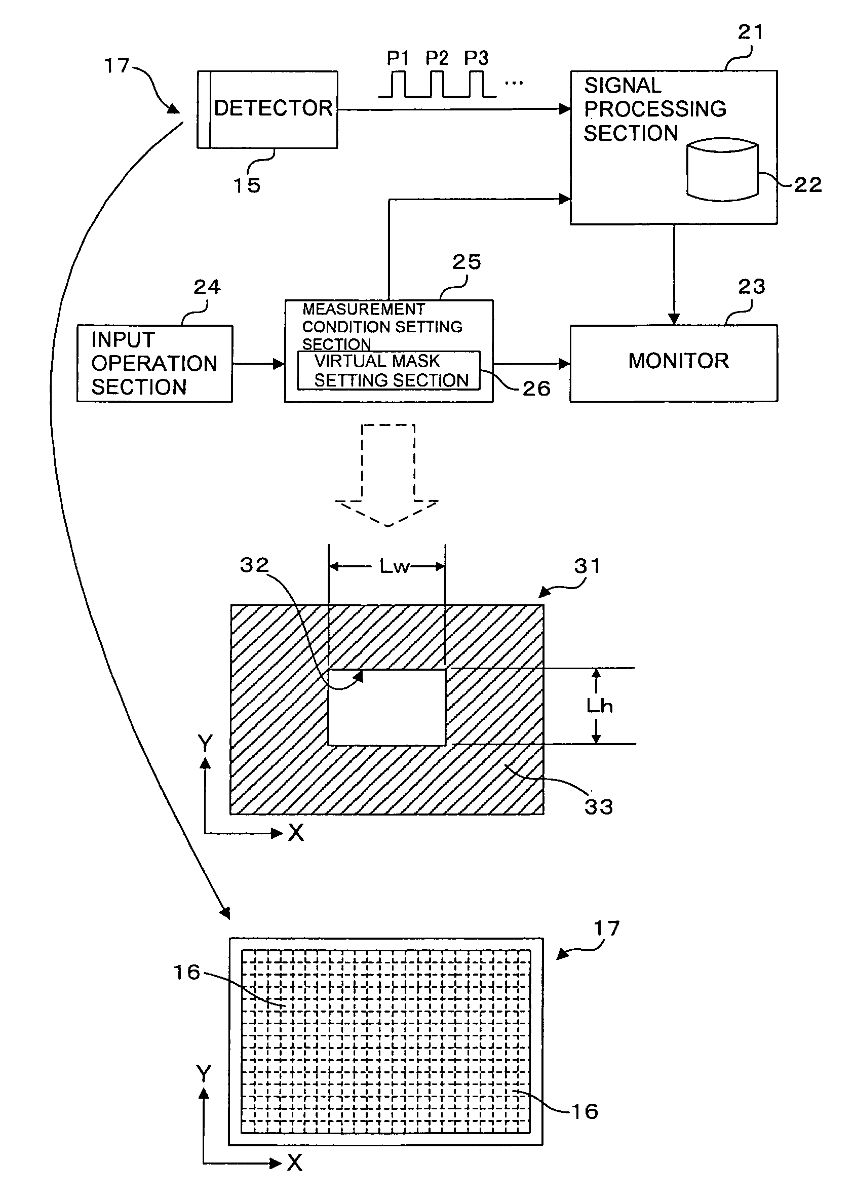
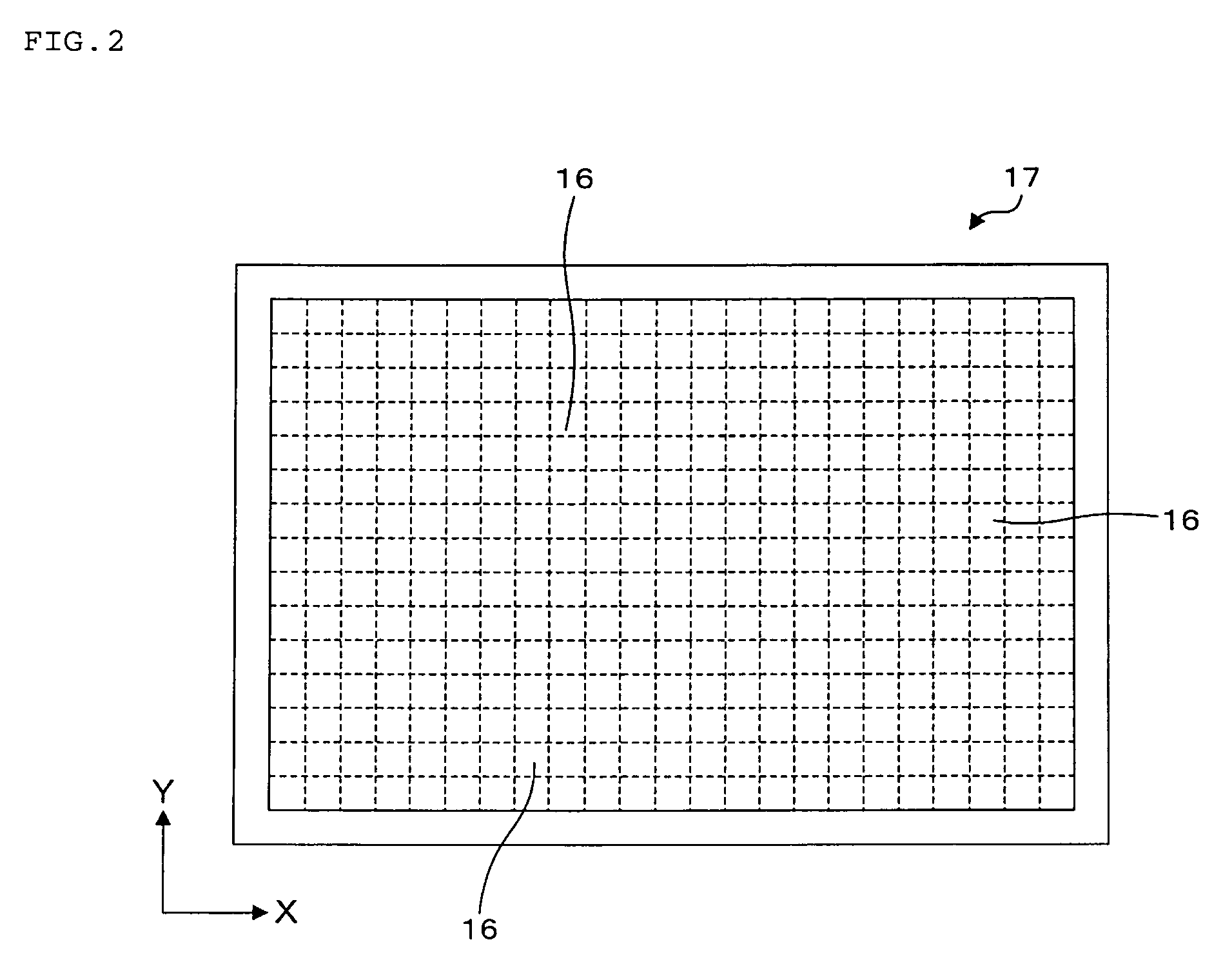
There is provided an X-ray diffraction apparatus configured to irradiate a sample S on a sample stage with X-rays generated from an X-ray source and detect the X-rays diffracted by a sample using a detector, including a virtual mask setting section and a signal processing section. The detector outputs detection signals according to intensity of the X-rays received by detection elements, for each of the plurality of detection elements forming a detection surface. The virtual mask setting section is capable of setting a virtual mask on the detection surface of the detector, and setting at least an opening dimension of the virtual mask as an opening condition of the virtual mask independently in an X direction and a Y direction. The signal processing section processes the detection signals outputted from the detector according to the opening condition of the virtual mask set in the virtual mask setting section.

Description

BACKGROUND[0001]1. Field of the Invention[0002]The present invention relates to an X-ray diffraction apparatus for irradiating a sample with X-rays and detecting the X-rays diffracted by the sample, and a method of measuring X-ray diffraction.[0003]2. Description of the Related Art[0004]As one of devices which analyze crystallinity and a crystal structure of a sample, an X-ray diffraction apparatus is known. The X-ray diffraction apparatus irradiates a sample with X-rays generated from an X-ray source, detects diffracted X-rays, and measures the intensity of the X-rays.[0005]FIG. 27 is a schematic diagram illustrating a constitutional example of a measurement optical system of a conventional X-ray diffraction apparatus.[0006]In FIG. 27, in a radiation direction of X-rays generated from an X-ray source 1, a paraboloidal multilayer mirror 2, a selection slit 3, an incidence soller slit 4, a length limiting slit 5, and an incidence slit 6 are disposed. An optical incidence system is co...

Claims


Application Information

Patent Timeline
Patent Type & Authority Patents(United States)
IPC IPC(8): H05G1/00G01N23/207
CPCG01N23/207G01N2223/3301
Inventor KOBAYASHI, SHINTAROMITSUNAGA, TORUKAJIYOSHI, KOICHIARAI, KAZUYOSHI
Owner RIGAKU CORP
Learn More