High-current switch

A high-current switch, electrical ground technology, applied in electrical switches, air switch parts, power devices inside switches, etc., can solve the problem of short switch life and achieve the effect of reliable closing or opening

Inactive Publication Date: 2014-11-26
SCHALTBAU GMBH
View PDF5 Cites 3 Cited by
  • Summary
  • Abstract
  • Description
  • Claims
  • Application Information

AI Technical Summary

Problems solved by technology

However, the elastically designed projections of the two fixed contacts are flared outwards in the cut-off state, so that when the switch is closed and opened due to friction, th

Method used


Image

  • High-current switch
  • High-current switch

Examples


Embodiment Construction

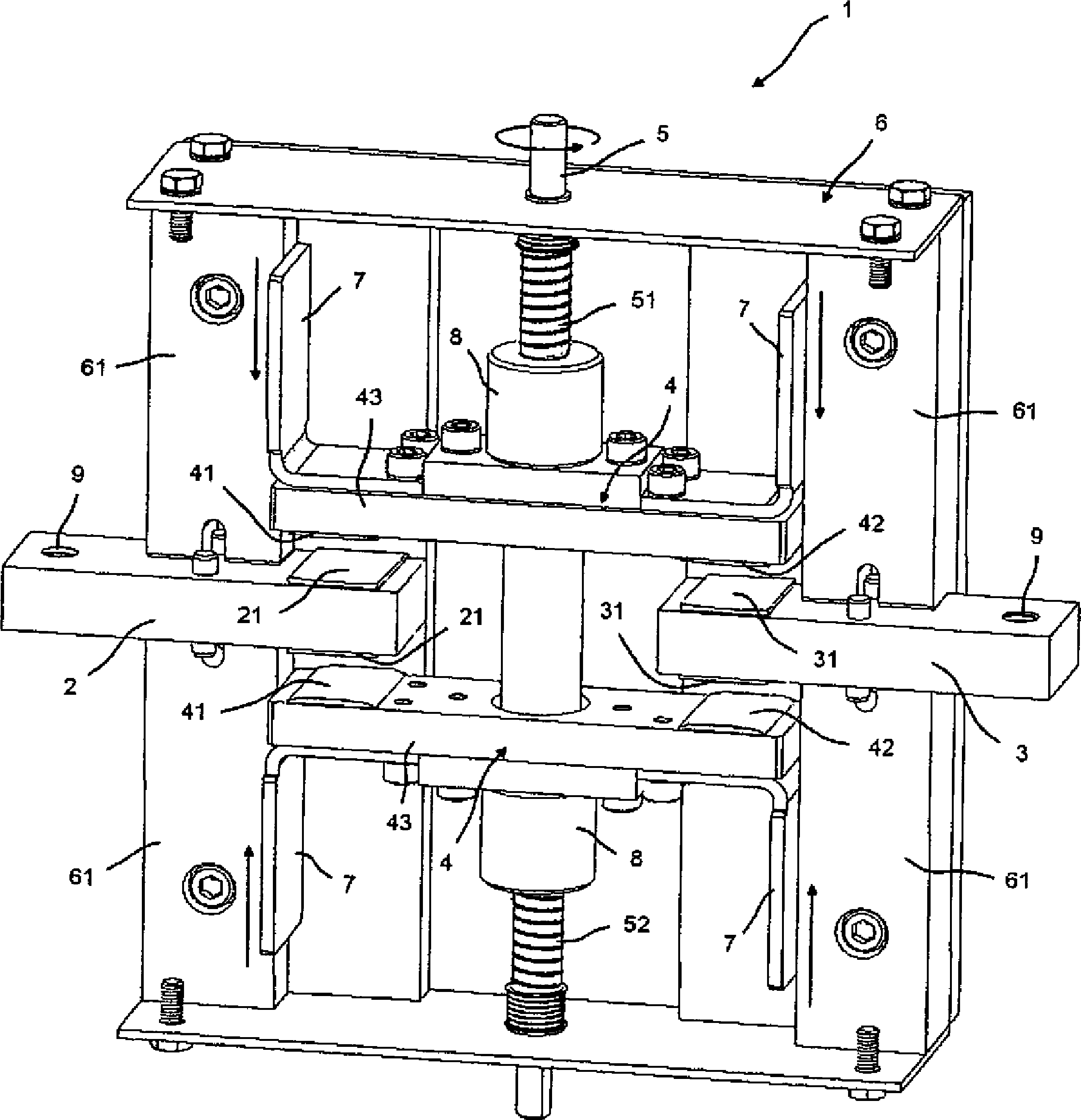
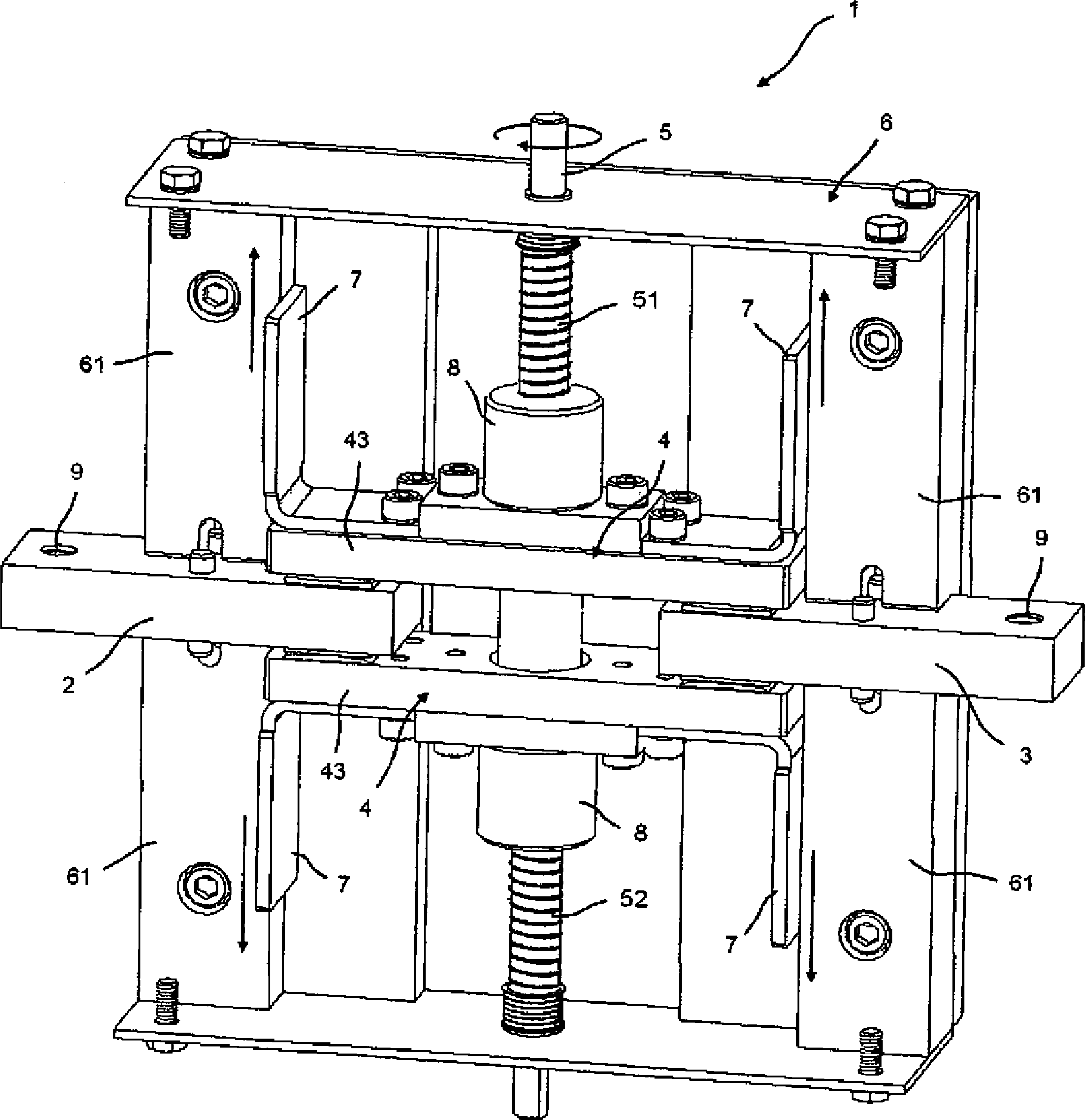
[0026] figure 1 and 2 Correspondingly in the closed position ( figure 1 ) and open position ( figure 2 ) shows an embodiment of a high current switch 1 according to the invention.

[0027] The housing 6 of the high-current switch 1 according to the invention is shown partly open, in order to allow observation of the internal structure of the switch.

[0028] The switch includes a first fixed contact 2 on the left and a second fixed contact 3 on the right. The two fixed contacts 2 and 3 are mounted at a distance from one another in the housing 6 of the switch 1 , wherein one end of the fixed contact 2 or 3 respectively protrudes from the housing 6 . Correspondingly, an electrical connection 9 is provided at this end, so that the switch 1 can be integrated into the circuit to be switched.

[0029] On switch 1 in the figure 1 In the closed position shown in , the two fixed contacts 2 and 3 are electrically connected to each other via two contact bridges 4 . Each of the tw...


PUM


Abstract

The invention relates to a high-current switch (1) comprising a first fixed contact (2), a second fixed contact spaced apart from the first fixed contact (3), and at least one contact bridge (4) that is movable relative to the two fixed contacts. Furthermore, an advancing device is provided for transferring the contact bridge (4) from an open position in which the two fixed contacts (2, 3) are not connected to one another into a closed position in which the contact bridge connects the two fixed contacts electrically to one another. The advancing device is also provided for pressing the contact bridge in the closed position against the two fixed contacts. According to the invention, the advancing device is designed without springs, wherein the rigidity of the contact bridge and the advancing device in the direction of the pressing force corresponds to a value of at least 50 000 kNmm2, and wherein the lowest natural frequency of the system consisting of the contact bridge and the advancing device in the direction of the pressing force is greater than 2000 Hz.

Description

technical field [0001] The invention relates to a high-current switch according to the preamble of independent claim 1 . Background technique [0002] A switch of this type comprises a first fixed contact and a second fixed contact spaced apart from the first fixed contact. Furthermore, a contact bridge (Kontaktbrücke) and a feeder (Zustellvorrichtung) that are movable relative to the two fixed contacts are provided in order to move the contact bridge from a switch in which the two fixed contacts are not connected to each other. The open position transitions into the closed position in which the contact bridge electrically connects the two fixed contacts to one another. Furthermore, the advancing device is provided for pressing the contact bridge in the closed position against the two fixed contacts. [0003] In switches, two fundamentally different construction types can generally be distinguished. In the first type of construction, the contact bridge is moved towards th...

Claims


Application Information

Patent Timeline
IPC IPC(8): H01H1/20H01H3/40
CPCH01H3/40H01H1/2025H01H2001/2033H01H1/50H01H3/24H01H1/20H01H31/02H01H31/24H01H1/502H01H2227/032
Inventor R.冯普龙德青斯基J.克内贝尔
Owner SCHALTBAU GMBH
Why Eureka
Try Eureka