
Self-moving pipe orifice correction hydraulic machine

A self-moving, hydraulic press technology, applied in the field of hydraulic presses, can solve the problems of low efficiency, high cost of movement and rotation, high risk factor of processing, etc., and achieve the effect of high processing efficiency and high safety factor

Active Publication Date: 2014-12-03
HEFEI METALFORMING MACHINE TOOL
View PDF6 Cites 1 Cited by
  • Summary
  • Abstract
  • Description
  • Claims
  • Application Information

AI Technical Summary

Problems solved by technology

, since the tonnage of the workpiece is generally about 20-50 tons, the cost of moving and rotating is high, the efficiency is very low, and the processing risk factor is large

Method used


Image

  • Self-moving pipe orifice correction hydraulic machine
  • Self-moving pipe orifice correction hydraulic machine
  • Self-moving pipe orifice correction hydraulic machine

Examples


Embodiment Construction

[0021] In order to make the object, technical solution and advantages of the present invention clearer, the present invention will be further described in detail below in conjunction with the accompanying drawings and implementation examples. It should be understood that the specific embodiments described here are only used to explain the present invention, not to limit the present invention.

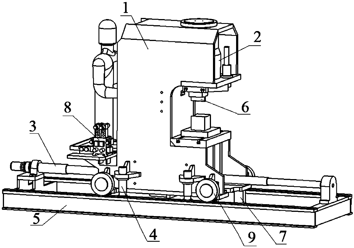
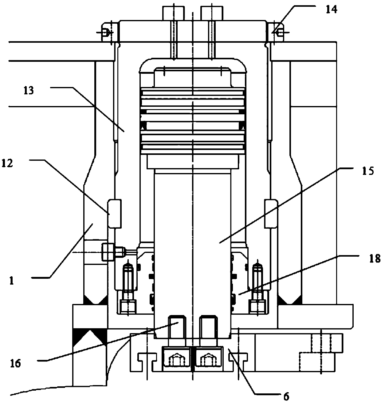
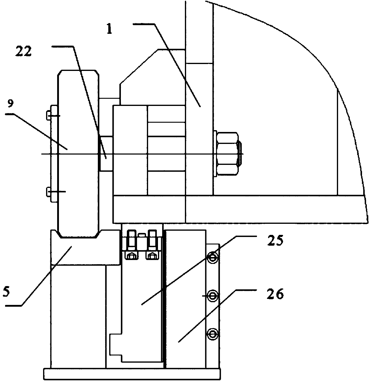
[0022] Please also refer to figure 1 , figure 2 , image 3 and Figure 4 , The self-moving nozzle correction hydraulic machine provided by the preferred embodiment of the present invention includes a body 1, a special-shaped indenter 6, a driver, a translation unit, and a lifting unit.

[0023] The special-shaped indenter 6 is installed on the body 1, and the driver drives the special-shaped indenter 6 to work. In this implementation example, the driver is a compact combination cylinder 2, please combine figure 2 , the fuselage 1 is connected to the compact combination cylinder 2...


PUM


Abstract

The invention discloses a self-moving pipe orifice correction hydraulic machine which comprises a machine body, a special-shaped pressing head mounted on the machine body, a driver driving the special-shaped pressing head to work, a translation unit driving the machine body to horizontally move, and an ascending and descending unit driving the machine body to longitudinally move. The translation unit comprises a pair of guide rails with V-shaped guide faces, at least three rollers with V-shaped rolling faces, and a screw driving device, the guide rails are parallel to each other, and the ascending and descending unit comprises a synchronous lifting mechanism and a separated-type hydraulic control system. The rollers are divided into two groups according to a principle that at least three points define a plane and mounted at the bottom of the machine body respectively, the rollers are mounted on the guide rails, and the V-shaped rolling faces are matched with the V-shaped guide faces of the corresponding guide rails to be capable of in reciprocating motion on a friction motion pair matching face formed by the V-shaped rolling faces and the V-shaped guide faces. The screw driving device drives the rollers to move along the guide rails and drives the machine body to be in translation, the synchronous lifting mechanism is mounted at the bottom of the machine body and used for lifting and lowering the machine body, and the separated-type hydraulic control system is fixed on the machine body and used for driving the synchronous lifting mechanism.

Description

technical field [0001] The invention relates to a hydraulic machine, in particular to a self-moving nozzle correction hydraulic machine. Background technique [0002] Large-diameter long steel pipes (10-25 meters) will appear horn-shaped nozzles or oval nozzles after deep-drawing and hot forging processes. At present, domestic manufacturers mostly use fixed-type calibration hydraulic presses for calibration. , because the tonnage of the workpiece is generally about 20 to 50 tons, the cost of moving and rotating is high, the efficiency is very low, and the processing risk factor is large. [0003] Therefore, it is necessary to develop a self-moving nozzle correction hydraulic machine, which can move freely in four degrees of freedom according to the size of the workpiece and the height of the corresponding rotation center, so as to adapt to the roundness correction of different workpieces. Contents of the invention [0004] In view of this, the present invention provides a...

Claims


Application Information

Patent Timeline
Patent Type & Authority Applications(China)
IPC IPC(8): B21D3/14
Inventor 柯烈强荣兆杰
Owner HEFEI METALFORMING MACHINE TOOL
Learn More