
A Ring Processing System

A processing system and ring technology, applied in metal processing, manufacturing tools, and other manufacturing equipment/tools, etc., can solve problems such as poor working conditions, low production efficiency, and loose fixation, and achieve high production efficiency, convenient operation, The effect of high degree of automation

Active Publication Date: 2016-08-24
ANHUI MASTEEL ENG & TECH GRP
View PDF4 Cites 0 Cited by
  • Summary
  • Abstract
  • Description
  • Claims
  • Application Information

AI Technical Summary

Problems solved by technology

[0007] Aiming at the potential safety hazards existing in the prior art and the problems of low production efficiency, poor working conditions for workers, and loose fixing when handling large ring parts, the present invention provides a ring part processing system, which can realize the automation of ring part production , improve production efficiency, use safety, save labor costs

Method used


Image

  • A Ring Processing System
  • A Ring Processing System
  • A Ring Processing System

Examples


Embodiment 1

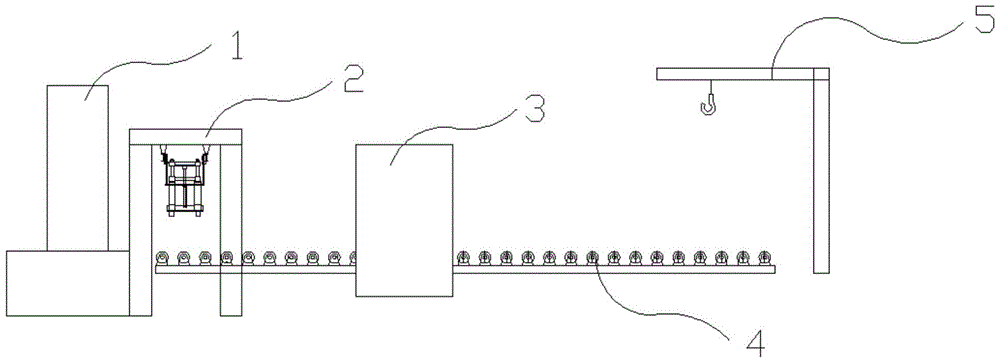
[0035] A ring processing system to achieve, the ring processing system such as figure 1 As shown, it includes a press, a ring rolling machine 1, a thermal printer 3, a cantilever crane 5, a heat treatment furnace, and also includes a ring unloading device 2 and a conveying roller table 4. The arrangement order of each link in the ring processing system is press, Ring rolling machine 1, conveying roller table 4, cantilever crane 5 and heat treatment furnace; ring rolling machine 1 and conveying roller table 4 are connected by a ring piece unloading device 2, and the height of conveying roller table 4 is lower than that of the exit of ring rolling machine 1 Height; Thermal printer 3 is located on conveying roller table 4.

[0036] The press machine is controlled by the press machine PLC, the ring rolling machine 1 is controlled by the ring rolling machine PLC, the thermal printer 3 is controlled by the thermal printer PLC, the ring piece unloading device 2 and the conveying roll...

Embodiment 2

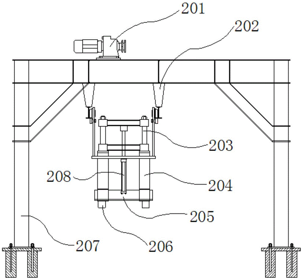
[0048] With embodiment 1, the difference is that one end of the hydraulic cylinder 208 is connected with the lower connecting rod 205 at the bottom end of the telescopic rod 203; Figure 5 As shown, the number of rollers 206 is two. The motor 201 drives the movement of the control device through chain transmission. Then, the same as in Embodiment 1, the hydraulic cylinder 208 drives the telescopic rod 203, the upper link and the roller 206 to move up and down. The expansion and contraction of the hydraulic cylinder 208 drives the roller 206 to move up and down. When the roller 206 reaches the center of the ring, the hydraulic cylinder 208 is extended, and the telescopic rod 203, the upper link, the lower link 205 and the roller 206 are all downward. movement, the roller 206 is inserted into the ring, and the motor 201 is started at this time, and the motor 201 drives the movement of the control device, thereby achieving the effect of moving the ring from the ring rolling mach...

Embodiment 3

[0050] Same as embodiment 1, the difference is that the number of rollers 206 can be five.


PUM


Abstract

The invention discloses a ring element processing system, and belongs to the fields of ring element heat processing and ring element transportation. The ring element processing system comprises a press machine, a ring rolling machine, a thermal printer, a cantilever crane, a heat treatment furnace, a ring element moving-out device and a conveying roller way, wherein the ranging sequence of each link of the ring element processing system is respectively the press machine, the ring rolling machine, the conveying roller way, the cantilever crane and the heat treatment furnace, the ring element moving-out device is arranged at a connecting part of the ring rolling machine and the conveying roller way, the height of the conveying roller way is smaller than that of an outlet of the ring rolling machine, and the thermal printer is positioned on the conveying roller way. The ring element processing system has the advantages that the production automation of ring elements can be realized, the production efficiency is improved, the use is safe, and the labor cost is reduced.

Description

[0001] The present invention is an application number: 2012103581619, and the name of the invention is: a ring processing system and its method and a ring removal device, and the application date is a divisional application of the patent applied on September 25, 2012. technical field [0002] The invention belongs to the field of ring thermal processing and ring transportation, and more specifically relates to a ring processing system. Background technique [0003] Ring products are widely used in various fields of the national economy, such as: flanges, ring gears, tires, etc. At present, the technological process of ring production is as follows: After the heated steel billet is upset and punched by a press, the billet is sent to the ring rolling machine by a manipulator for rolling. The billets are rolled into rings on a ring rolling machine. At this time, the diameter of the ring can reach and even larger, currently up to Due to the large diameter of the ring, there...

Claims


Application Information

Patent Timeline
Patent Type & Authority Patents(China)
IPC IPC(8): B23P15/00B23P23/00B23Q7/00
CPCB23P23/06B23Q7/00
Inventor 李伏武蔡长生高建芳
Owner ANHUI MASTEEL ENG & TECH GRP
Learn More