Bionic jellyfish robot driven by parallelly connected mechanical arms

A technology of mechanical arms and robots, which is applied in the direction of manipulators, water action propulsion components, ship propulsion, etc., can solve the problems of small driving force, small movement range, and unsuitability for complex marine environments, so as to reduce the weight of the whole machine and reduce the deformation range. Control, improve the effect of operability and flexibility

Active Publication Date: 2014-12-03
严格集团股份有限公司
View PDF6 Cites 12 Cited by
  • Summary
  • Abstract
  • Description
  • Claims
  • Application Information

AI Technical Summary

Problems solved by technology

[0007] The purpose of the present invention is to solve the problems that existing bionic jellyfish robots have small motion range, small driving force, and are not suitable for complex marine environments

Method used


Image

  • Bionic jellyfish robot driven by parallelly connected mechanical arms
  • Bionic jellyfish robot driven by parallelly connected mechanical arms
  • Bionic jellyfish robot driven by parallelly connected mechanical arms

Examples


specific Embodiment approach 1

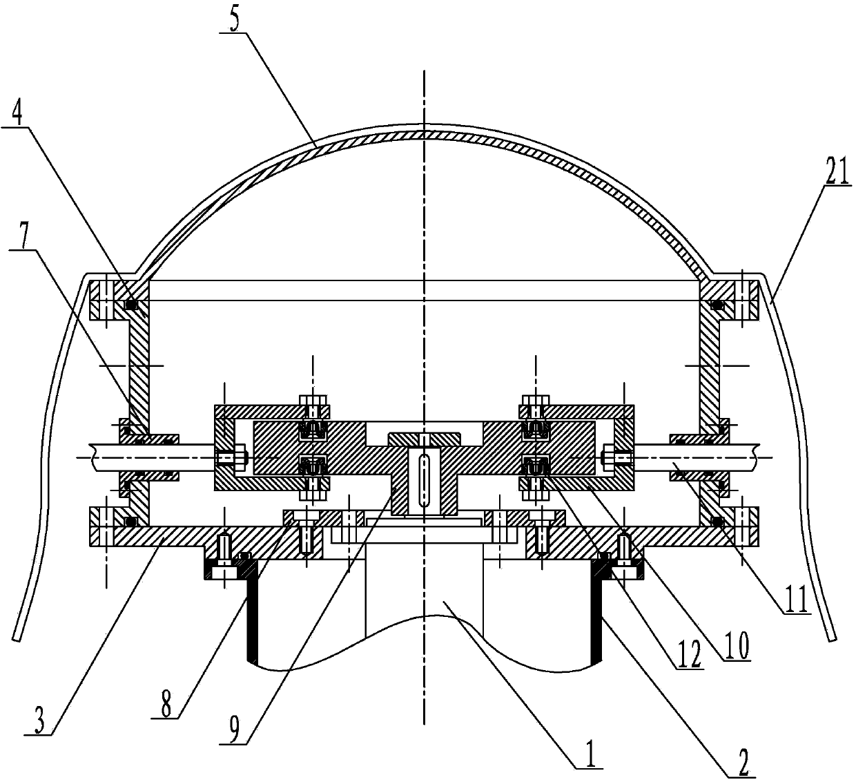
[0016] Specific implementation mode one: combine Figure 1-Figure 6 Describe this embodiment, a bionic jellyfish robot driven by a parallel mechanical arm in this embodiment includes a drive unit 1, a base 2, a base 3, a sleeve 4, a streamlined end cover 5, a motor connecting plate 8, a cam drive plate 9, A plurality of sliding connection seats 10, a plurality of mechanical arm driving rods 11, a plurality of driving rod guide flanges 7, a plurality of roller shaft parts 12 and a plurality of flexible mechanical arms, a streamlined end cover 5, a sleeve 4, a base 3 and The base 2 is connected sequentially from top to bottom, one end of the drive unit 1 is connected through the motor connection plate 8 installed on the base 3, the cam drive disc 9 is set on the output shaft of the drive unit 1 in the sleeve 4, and the cam drive disc 9 A track groove is respectively provided along the outer contour line on the upper and lower end faces of the upper and lower ends, and the contou...

specific Embodiment approach 2

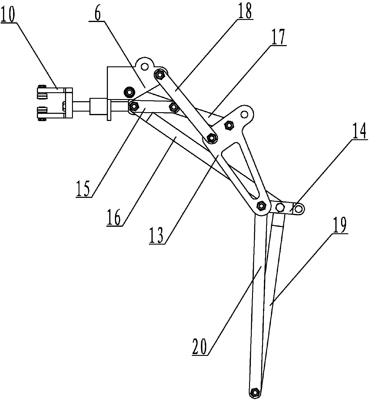
[0019] Specific implementation mode two: combination Image 6 To illustrate this embodiment, the bionic jellyfish robot of this embodiment also includes a plurality of horn bases 6 , and each flexible robotic arm is connected to each mechanical arm driving rod 11 through a horn base 6 . With such a setting, the movement is more flexible. Other compositions and connections are the same as in the first embodiment.

specific Embodiment approach 3

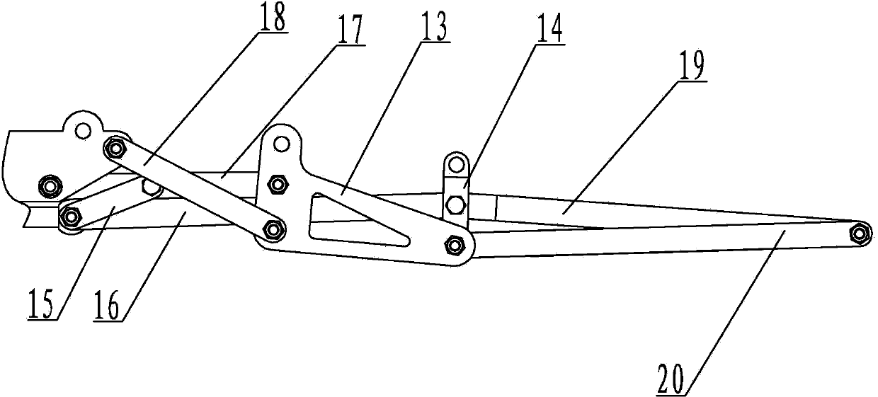
[0020] Specific implementation mode three: combination Figure 2-Figure 3 This embodiment will be described. The plurality of flexible robotic arms in this embodiment are all single-degree-of-freedom three-joint series mechanisms. So set, the movement is flexible. Other compositions and connections are the same as those in Embodiment 1 or Embodiment 2.


PUM


Abstract

The invention relates to a bionic jellyfish robot, provides a bionic jellyfish robot driven by parallelly connected mechanical arms, and aims to solve the problems that the conventional bionic jellyfish robot is small in moving amplitude, small in driving force and unsuitable for the complicated marine environment. A streamline end cover, a sleeve, a pedestal and a base are sequentially connected; one end of a driving unit is connected through a motor connecting plate mounted on the pedestal; a cam driving disc is mounted on the output shaft of the driving unit inside the sleeve in a sleeving manner; a track groove is formed in each of the upper end surface and the lower end surface of the cam driving disc along the outer contour line of the cam driving disc; the contour shape of each track groove is a concave-convex contour curve; a plurality of sliding connecting bases are in sliding joint with the track grooves of the cam driving disc 9 in an annular arrayed manner through a plurality of roller shaft components; one end of each mechanical arm drive rod is connected with one sliding connecting base, and the other end of each mechanical arm drive rod is in flexible connection with a flexible mechanical arm. The bionic jellyfish robot is used for unmanned underwater transportation.

Description

technical field [0001] The invention relates to a bionic jellyfish robot, in particular to a bionic jellyfish robot driven by parallel mechanical arms. Background technique [0002] Unmanned underwater vehicle system (Unmanned Underwater Vehicle) has been rapidly developed in recent years along with the pace of human exploration and development of the ocean. Among them, machines that use fish and other aquatic organisms as propulsion system bionic prototypes are receiving more and more attention. more attention. Compared with traditional wavy swimming fish, jellyfish have higher mobility flexibility, environmental adaptability and target concealment, and also have an efficient flow field energy utilization mechanism, which is especially suitable for deep diving in the ocean, observation of ocean currents, Bionic prototypes of underwater vehicles such as target detection and weapon delivery. [0003] As a typical prototype of jet propulsion, jellyfish is one of the oldest s...

Claims


Application Information

Patent Timeline
IPC IPC(8): B63H1/38B25J11/00
Inventor 陈维山董帝渤韩臻博王鹏刘军考石胜君侯珍秀
Owner 严格集团股份有限公司
Why Eureka
Try Eureka