

Efficient motor shaft
A motor shaft, high-efficiency technology, applied in the direction of shafts, shafts and bearings, mechanical equipment, etc., can solve problems that affect work efficiency, offset, gear or bearing beating, etc., and achieve the effect of improving work efficiency
Inactive Publication Date: 2014-12-03
CHANGZHOU RIFA PRECISION MACHINERY PLANT
View PDF5 Cites 2 Cited by
- Summary
- Abstract
- Description
- Claims
- Application Information
AI Technical Summary
Problems solved by technology
[0002] When the motor shaft is in use, it is mainly used to carry the gears and bearings sleeved on the motor shaft for high-speed rotation, but the structure of the currently used motor shaft is only a simple cylindrical shaft. During use, the high-speed rotation of the motor shaft When the gears or bearings are driven to rotate at high speed, the gears or bearings tend to jump and shift, which greatly affects the work efficiency and the use of the machine.
Method used
View moreImage
Smart ImageViewing Examples

Examples
Embodiment Construction
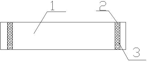
[0010] Such as figure 1 It is a structural schematic diagram of the present invention, a high-efficiency motor shaft, including a motor shaft body 1, a sleeve 2 is respectively provided on the motor shaft body 1 near the front end and the rear end, and there are several raised convex surfaces on the sleeve 2 3. Preferably, the material of the sleeve 2 is elastic rubber.
[0011] In the present invention, a sleeve 2 is sheathed on the motor shaft body 1, and the sleeve 2 has a raised convex surface 3, which can prevent the gears sleeved on the motor shaft from bouncing and shifting during operation, greatly improving work efficiency.
Login to View More PUM
 Abstract
The invention relates to the technical field of motor devices, and in particular relates to an efficient motor shaft. The efficient motor shaft comprises a motor shaft body, wherein sleeves are respectively arranged on the positions, close to the front end and rear end of the motor shaft body, on the motor shaft body, and each sleeve is provided with a plurality of raised surfaces. The sleeves are made of elastic rubber. The sleeves are arranged on the shaft body in a sleeving manner and provided with the raised surfaces, so that a gear arranged on the motor shaft in the sleeving manner does not jump or shift during running and the working efficiency is greatly improved.
Description
technical field [0001] The invention relates to the technical field of motor devices, in particular to a high-efficiency motor shaft. Background technique [0002] When the motor shaft is in use, it is mainly used to carry the gears and bearings sleeved on the motor shaft for high-speed rotation, but the structure of the currently used motor shaft is only a simple cylindrical shaft. During use, the high-speed rotation of the motor shaft When the gears or bearings are driven to rotate at high speed, the gears or bearings tend to jump and shift, which greatly affects the work efficiency and the use of the machine. Contents of the invention [0003] In order to overcome the shortcomings of the existing technology, the invention provides a high-efficiency motor shaft. [0004] The technical solution adopted by the present invention to solve its technical problems is: a high-efficiency motor shaft, including a motor shaft body, sleeves are respectively arranged on the position...
Claims
Login to View More Application Information
Patent Timeline
 Patent Type & Authority Applications(China)
IPC IPC(8): F16C3/02
Inventor 王富生
Owner CHANGZHOU RIFA PRECISION MACHINERY PLANT