Adjusting device of microwave antenna

An adjustment device and microwave antenna technology, which is applied in the field of communication, can solve the problems of low adjustment accuracy, signal jumping, and signal string movement, etc., and achieve the effects of continuous microwave signal changes, easy operation, and high adjustment accuracy

Active Publication Date: 2014-06-04
HUAWEI TECH CO LTD
View PDF4 Cites 2 Cited by
  • Summary
  • Abstract
  • Description
  • Claims
  • Application Information

AI Technical Summary

Problems solved by technology

[0007] The purpose of the present invention is to provide a microwave antenna adjustment device, which is used to solve the problems of signal jumping caused by nonlinear adjustment, signal string vibration during fastening, and low adjustment accuracy in the prior art.

Method used


Image

  • Adjusting device of microwave antenna
  • Adjusting device of microwave antenna
  • Adjusting device of microwave antenna

Examples


Embodiment Construction

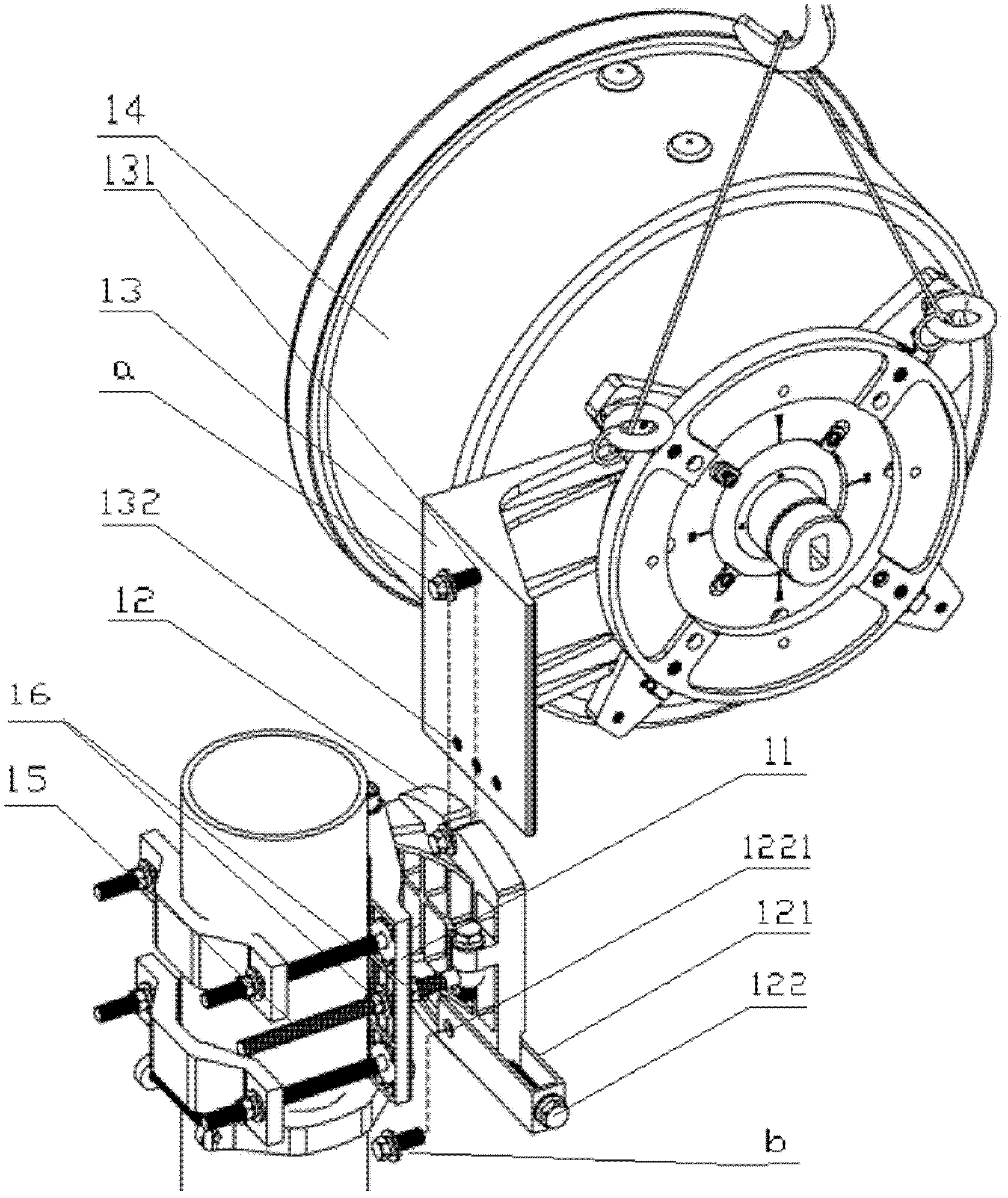
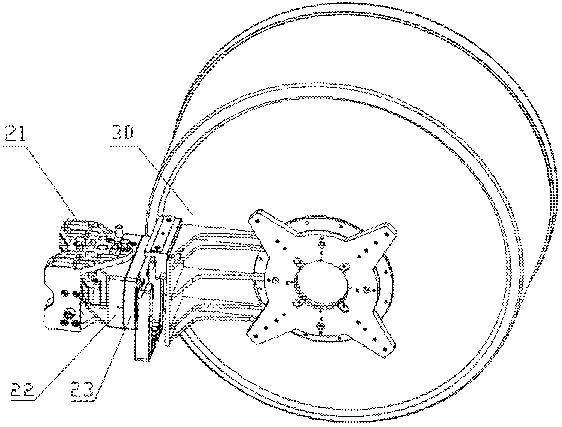
[0025] The core of the present invention is to provide a microwave antenna adjustment device, which adjusts the position of the microwave antenna through a worm gear mechanism, and realizes linear transmission. During the adjustment process, the microwave signal is continuous without jumping, and the adjustment accuracy is high, and the operation is simple.

[0026] In order to enable those skilled in the art to better understand the technical solutions of the present invention, the present invention will be further described in detail below in conjunction with the accompanying drawings and specific embodiments.

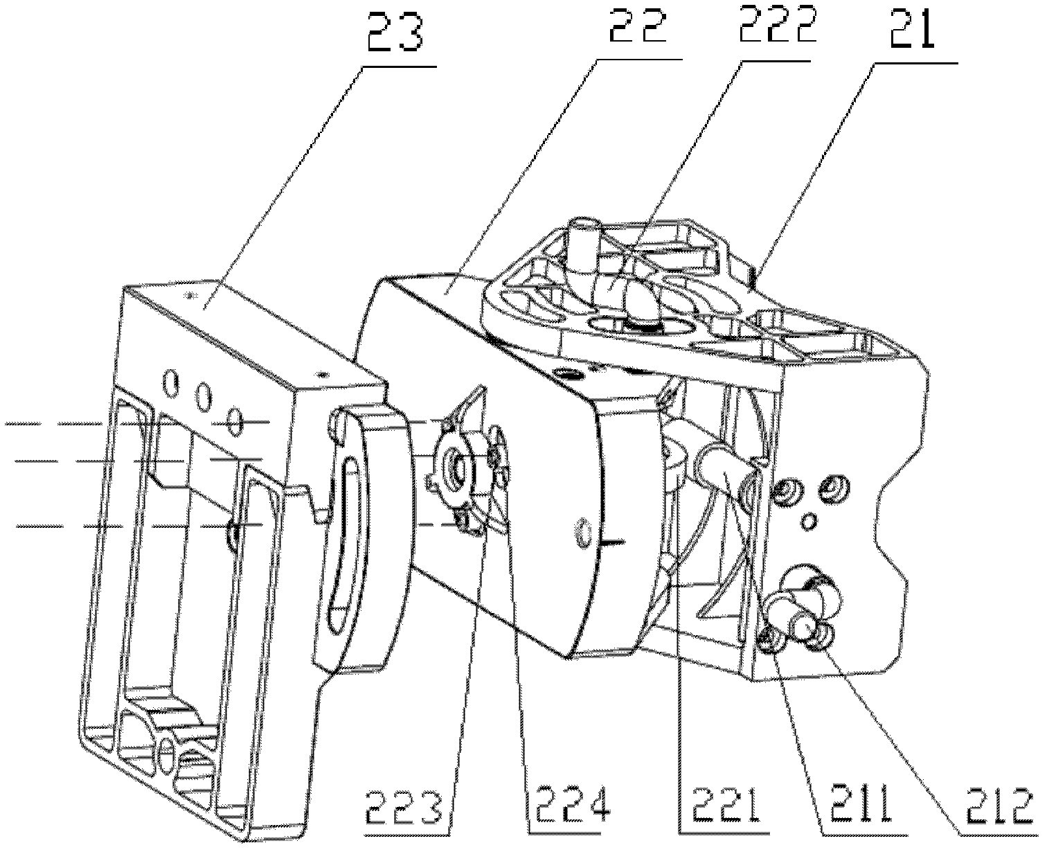
[0027] Please refer to figure 2 and image 3 , figure 2 It is a structural schematic diagram of a specific embodiment of the microwave antenna adjustment device provided by the present invention, and the figure also shows the microwave antenna connected to the adjustment device; image 3 for figure 2 Schematic diagram of the structure of the regulating device. ...


PUM


Abstract

A regulating device for a microwave antenna, comprising a supporting element hinged via a first hinge shaft, and a mounting element connected to the microwave antenna. The supporting element is provided with a first worm. The regulating device also comprises a first worm drive matching the first worm and fixed to the mounting element. The rotation axis of the first worm drive overlaps the axis of the first hinge shaft. The regulating device also comprises a first driver device for driving the first worm into rotation. In the regulating device, the worm drive-and-worm mechanism is used to drive the mounting element into rotation relative to the supporting element, thus driving into rotation the microwave antenna connected to the mounting element, allowing convenient operation. Also, as the worm drive-and-worm mechanism is transmitted linearly, the position of the microwave antenna is adjusted linearly, microwave signal transformations are continuous and pulse-free, and the regulation is of great precision. In addition, the worm drive-and-worm mechanism is provided with stable adjustment, compared to the prior art of threaded rod drive, the solution does not employ threaded rods, and obviates the need for the processing of an oversized through-hole, thus avoiding the generation of serial motion of signals when screws are fastened on two sides of the oversized through-hole.

Description

technical field [0001] The invention relates to the technical field of communication, in particular to an adjusting device for a microwave antenna. Background technique [0002] In the field of communication technology, microwave is a commonly used point-to-point wireless transmission technology, which is generally used in scenarios where the location is relatively far away and it is inconvenient to lay cables. The signal radiated by the microwave is divided into the main lobe and the side lobe. In order to ensure the signal propagation quality between a pair of microwaves, it is required to adjust the position of the microwave antenna until the two main lobes of the microwave overlap each other in space. [0003] Please refer to figure 1 , figure 1 It is a structural schematic diagram of a microwave antenna and its adjusting device in the prior art. The adjustment device in the prior art includes a mount 12 for mounting a microwave antenna 14 and a support 11 fixed on th...

Claims


Application Information

Patent Timeline
Patent Type & Authority Patents(China)
IPC IPC(8): H01Q3/08
CPCH01Q1/125
Inventor 柯有和张伟王彬
Owner HUAWEI TECH CO LTD
Why Eureka
Try Eureka