Rail outline and undulatory wear sensor positioning mechanism for tracking central line of top of steel rail

A sensor, centerline technology, applied in the field of three-dimensional flexible positioning mechanism, can solve problems such as front and rear swing

Inactive Publication Date: 2015-04-08
CHINA NORTH VEHICLE RES INST
View PDF5 Cites 2 Cited by
  • Summary
  • Abstract
  • Description
  • Claims
  • Application Information

AI Technical Summary

Problems solved by technology

[0005] The invention solves the problem of the front and rear positioning wheels swinging back and forth during the traveling process, so that it can move steadily along the center of the rail with the positioning mechanism, and ensures that the sensor probe is always on the center line of the rail without jumping when the train advances

Method used


Image

  • Rail outline and undulatory wear sensor positioning mechanism for tracking central line of top of steel rail
  • Rail outline and undulatory wear sensor positioning mechanism for tracking central line of top of steel rail
  • Rail outline and undulatory wear sensor positioning mechanism for tracking central line of top of steel rail

Examples


Embodiment Construction

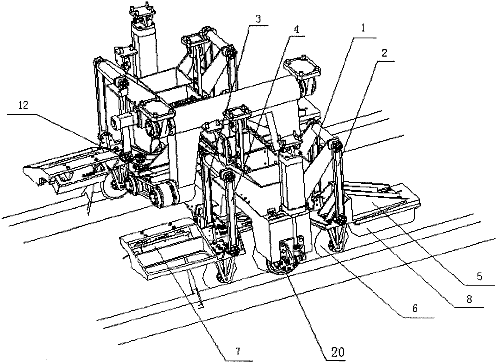
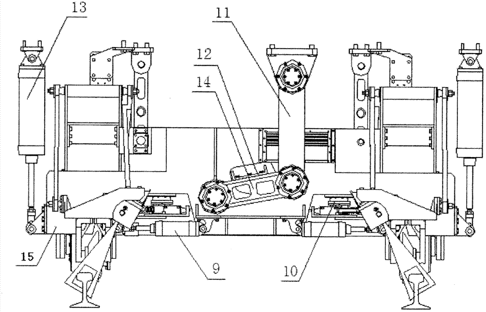
[0012] The track profile corrugation sensor positioning mechanism of the present invention, which tracks the center line of the rail top, is installed on the chassis of the detection car and moves smoothly with the train. Its main structure is as follows: figure 1 , figure 2 Shown: including main shaft beam 11, synchronous support 12, two cantilever frames 14, support beam 15 and the support wheel 20 that is arranged on the left and right bottom of support beam 15, all are provided with four connecting rods 1-4 on each side guide rail, positioning Wheel support 5, positioning wheel 6, positioning wheel supporting cylinder 9, "Z" shape connecting rod 10, master cylinder 13; supporting wheel 20 moves along the left and right sides guide rails.

[0013] The rail profile sensor 7 and the corrugation sensor 8 are respectively installed at the front and rear ends of the positioning wheel bracket 5. The top ends of the four connecting rods are all connected above the support beam 15...


PUM


Abstract

The invention discloses a rail outline and undulatory wear sensor positioning mechanism for tracking a central line of the top of a steel rail. The positioning mechanism is arranged on a detection vehicle chassis and stably moves along with a train; and four connecting rods of the positioning mechanism are driven through two main cylinders, so that the entire detection mechanism can be lifted or dropped. When not in work, the positioning mechanism is lifted and is fixedly arranged on the detection vehicle chassis; and when in work, a rail is tightly pressed by the positioning mechanism through the cylinder to keep in close contact with the rail face. A rail outline sensor and an undulatory wear sensor are arranged on two sides of a positioning wheel bracket respectively; and when in work, the positioning wheels are closely attached to the rail through a positioning wheel supporting cylinder. According to the positioning mechanism, a synchronous bracket is additionally arranged, so that the problem of back-forth swing during advancing of the front and rear positioning wheels is solved, and the front and rear positioning wheels can stably move along the center of the rail with the detection device.

Description

technical field [0001] The invention is mainly applied to the fixing of various rail profiles and corrugation sensors, and in particular relates to a three-dimensional flexible positioning mechanism. Background technique [0002] my country's railway construction has achieved rapid development in recent years, and track damage such as rail wave wear has become an increasingly serious problem. During the running of the train, the dynamic effect of the wheelset and the track, the natural environment and the quality of the rail itself will cause damage such as wave wear on the surface of the rail. Rail wave abrasion, referred to as wave abrasion, is a major type of rail damage. It is a periodic wave-like irregularity on the surface of the rail along the longitudinal direction. [0003] Rail wave wear is one of the main causes of noise and changes in wheel-rail interaction force. If the rail wave wear cannot be detected and maintained in time, the deterioration of the wheel-ra...

Claims


Application Information

Patent Timeline
Patent Type & Authority Patents(China)
IPC IPC(8): B61K9/00
Inventor 章文峰白璐边永昌王志刚黄敏陈建义侯茂新戚于飞李欣颜杨晓宇倪永亮庞凤颖
Owner CHINA NORTH VEHICLE RES INST
Why Eureka
Try Eureka