Hydraulic balance control method and system for secondary circulation
A technology of hydraulic balance and control method, applied in the field of heating, which can solve the problems of increasing system resistance, inaccurate hydraulic distribution adjustment, and high design cost
- Summary
- Abstract
- Description
- Claims
- Application Information
AI Technical Summary
Problems solved by technology
Method used
Image
Examples
Embodiment 1
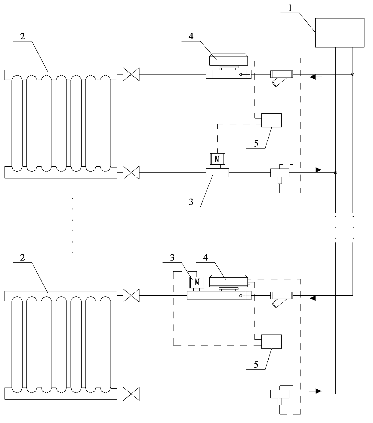
[0032] See figure 1 , which shows a schematic diagram of the principle of the secondary network hydraulic balance control system shown in the first embodiment. In order to clearly show the necessary coordination relationship of the main functional components of the control system, figure 1 Two end users are used as an example to illustrate its control principle. Each end user is connected in parallel with the heat exchange station 1 of the secondary network, and each end user uses a heating terminal 2 for illustration.
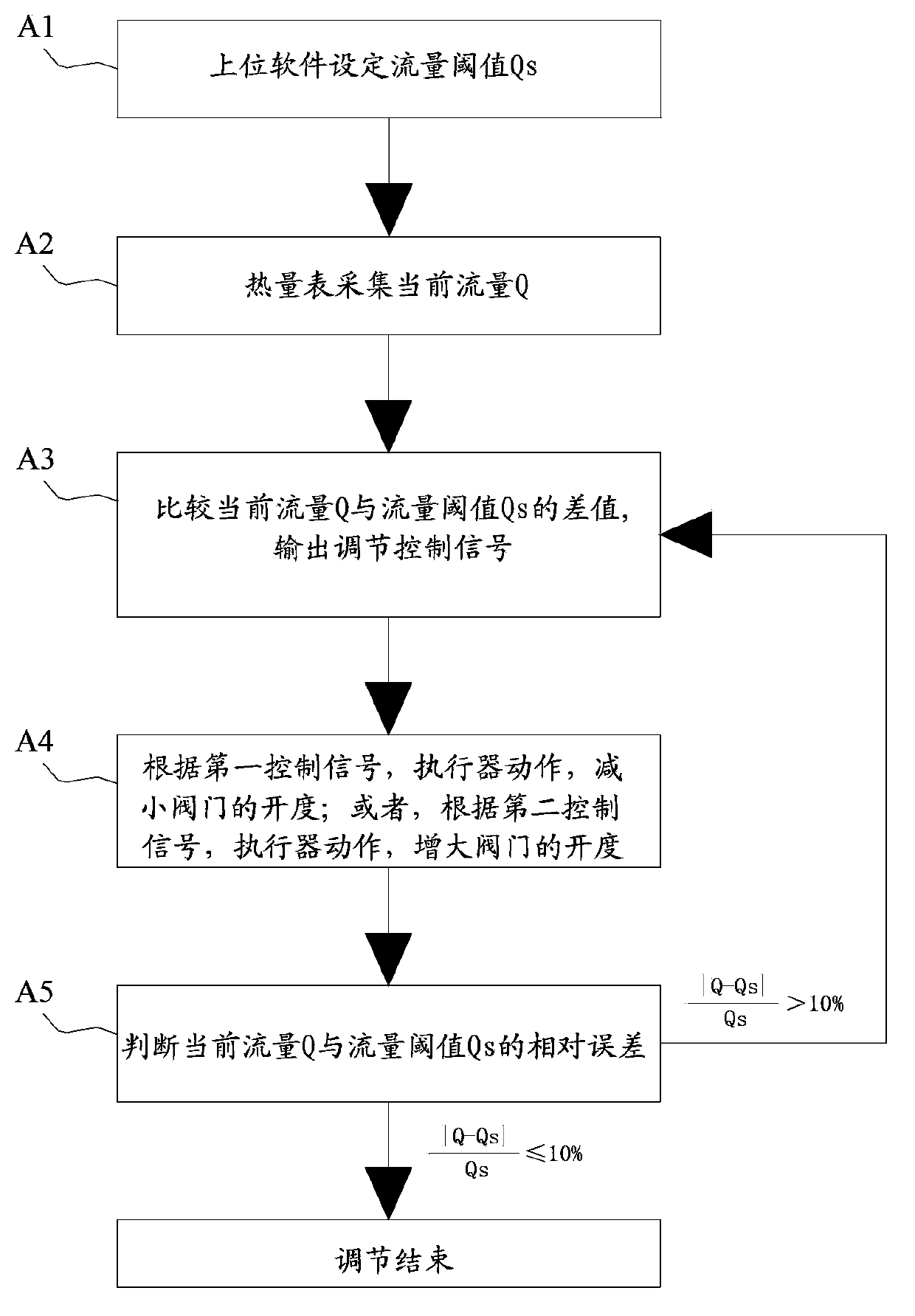
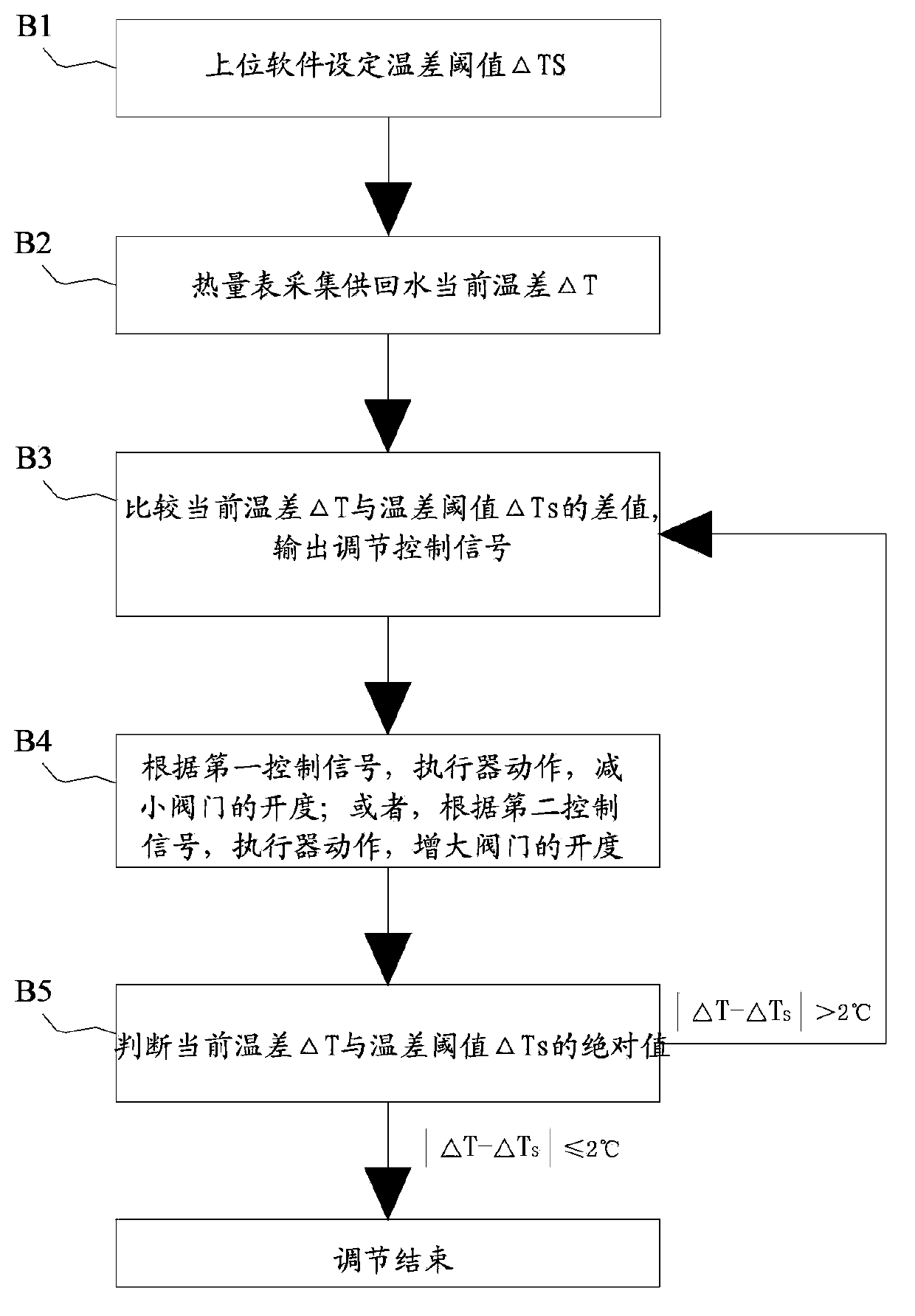
[0033] Corresponding to each end user, the secondary network hydraulic balance control system is equipped with a set of components. As shown in the figure, corresponding to each end user, it includes an electric regulating valve 3 and a flow collection device 4; wherein, the electric regulating valve 3 is set on the outlet and return water pipeline of the corresponding end user, and its opening can be adjusted The flow of hot water entering the home of the e...
Embodiment 2
[0059] See Figure 4 , which shows a schematic diagram of the principle of the secondary network hydraulic balance control system shown in the second embodiment. In order to clearly show the necessary coordination relationship of the main functional components of the control system, Figure 4 Only one end user is used as an example to illustrate its control principle, and the end user uses two heating terminals 2 for illustration.
[0060] The difference between the secondary network hydraulic balance control system described in this solution and the first embodiment is that a temperature control valve 6 is added on the basis of the first embodiment. The temperature control valve 6 is set at the heating terminal 2 of the corresponding end user according to the needs of the user, so as to control the flow of the heating terminal 2 in real time; the temperature control valve 6 can be realized by using the existing technology, and will not be described in detail herein.
[0061...
Embodiment 3
[0064] See Figure 5 , which shows a schematic diagram of the principle of the secondary network hydraulic balance control system shown in the third embodiment. In order to clearly show the necessary coordination relationship of the main functional components of the control system, Figure 5 Only one end user is used as an example to illustrate its control principle, and the end user uses two heating terminals 2 for illustration.
[0065] The difference between the secondary network hydraulic balance control system described in this program and the first embodiment is that, on the basis of the first embodiment, a temperature control panel 7 is additionally provided in the corresponding end user room, and the temperature control panel 7 is the same as the existing one. All technologies have the same working principle, and can realize temperature control function and management function (user arrears), and can output mandatory instructions of corresponding end users to the cont...
PUM
 Abstract
Description
Claims
Application Information
 - R&D
- Intellectual Property
- Life Sciences
- Materials
- Tech Scout
- Unparalleled Data Quality
- Higher Quality Content
- 60% Fewer Hallucinations
Browse by: Latest US Patents, China's latest patents, Technical Efficacy Thesaurus, Application Domain, Technology Topic, Popular Technical Reports.
© 2025 PatSnap. All rights reserved.Legal|Privacy policy|Modern Slavery Act Transparency Statement|Sitemap|About US| Contact US: help@patsnap.com


