Point contact type fretting fatigue test device and point contact type fretting fatigue test method

A technology of fretting fatigue and test equipment, which is applied in the direction of measuring devices, instruments, scientific instruments, etc., can solve the problems of unadhesive area, slip area and open area research, difficulties in applying tribological theory, and in-depth research on fretting fatigue theory Constraints and other issues

Active Publication Date: 2014-12-03
SOUTHWEST JIAOTONG UNIV
View PDF7 Cites 34 Cited by
  • Summary
  • Abstract
  • Description
  • Claims
  • Application Information

AI Technical Summary

Problems solved by technology

Fretting fatigue is a combined process of fretting wear and fatigue, involving three failure modes of friction and wear, fatigue and corrosion. The main factors affecting fretting fatigue are contact stress, frequency, displacement amplitude and stress amplitude, etc.; Fretting fatigue must be combined with tribology theory and fatigue theory. For fretting fatigue experimental research, most of them focus on tension and compression fretting fatigue and torsional fretting fatigue, and mostly use physical research or surface contact for research, which can be better used Fatigue theory, while the application of tribological theory is relatively difficult, and it is impossible to study the sticking zone, slipping zone and opening zone in fretting wear
At the same time, the tension-torsion compound fretting fatigue mode is relatively rare, and the theoretical research cannot be carried out better by physical research or surface contact.
However, the existing technology cannot solve the problem of equipment well, and the in-depth research on fretting fatigue theory will be restricted

Method used


Image

  • Point contact type fretting fatigue test device and point contact type fretting fatigue test method
  • Point contact type fretting fatigue test device and point contact type fretting fatigue test method
  • Point contact type fretting fatigue test device and point contact type fretting fatigue test method

Examples


Embodiment 1

[0030] The fatigue testing machine mentioned in this embodiment is the MTS809 electro-hydraulic servo testing machine.

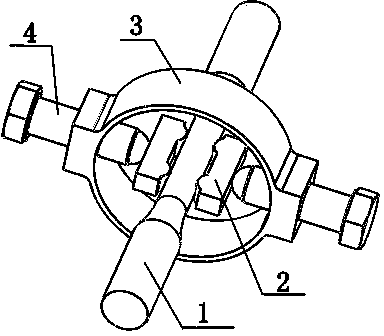
[0031] Such as figure 1 , figure 2 As shown, a point contact fretting fatigue test device includes a fretting bridge 2 in direct contact with the sample 1, a loading ring 3 whose ring surface is perpendicular to the axial direction of the sample 1, passes through the ring wall of the loading ring and fretting The loading bolt 4 contacted by the bridge 2, and the assembly frame 5 arranged in the loading ring 3, the sample 1 passes through the center of the annulus of the loading ring 3, and the contact surface between the fretting bridge 2 and the sample 1 is set There are convex arc-shaped fretting bridge feet, and the loading ring 3 is provided with strain gauges and connected with strain gauges.

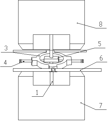
[0032] Such as Figure 6 , Figure 7 As shown, a symmetrical side of the assembly frame 5 is hollowed through, and the hollow through cavity is used to pla...

Embodiment 2

[0044] The fatigue testing machine mentioned in this embodiment is the MTS809 electro-hydraulic servo testing machine.

[0045] Such as figure 1 , figure 2 As shown, a point contact fretting fatigue test device includes a fretting bridge 2 in direct contact with the sample 1, a loading ring 3 whose ring surface is perpendicular to the axial direction of the sample 1, passes through the ring wall of the loading ring and fretting The loading bolt 4 contacted by the bridge 2, and the assembly frame 5 arranged in the loading ring 3, the sample 1 passes through the center of the annulus of the loading ring 3, and the contact surface between the fretting bridge 2 and the sample 1 is set There is a convex arc-shaped fretting bridge foot, and the loading bolt 4 is provided with a strain gauge and is connected with a strain gauge.

[0046] Such as Figure 6 , Figure 7 As shown, a symmetrical side of the assembly frame 5 is hollowed through, and the hollow through cavity is used ...

Embodiment 3

[0057] In this embodiment, the structure of the point contact fretting fatigue test device is the same as that in Embodiment 2.

[0058] Such as Figure 8 As shown, in this embodiment, the sample is LZ50 axle steel, and the fretting fatigue test under circular path loading is carried out on the MTS809 type tension-torsion combined electro-hydraulic servo material testing machine with a point-contact fretting fatigue test device added. The pull-down torsional compound fretting in the circular path is carried out under the control load mode in the axial and torsional directions, and the axial stress amplitudes of 300Mpa, 400Mpa, 450Mpa and 500Mpa are respectively applied to the sample, 173MPa, 231MPa, 260MPa and 289MPa The torsional stress amplitude, the contact pressure is controlled and kept constant by loading bolts and strain gauges, the axial and torsional frequencies are 1Hz, the ratio of axial and torsional stress is r=0.1, the loading waveform is sine wave, and the test ...


PUM


Abstract

The invention discloses a point contact type fretting fatigue test device and a point contact type fretting fatigue test method. The test device comprises a fretting bridge in direct contact with a sample, a loading ring with a ring surface perpendicular to the axial direction of the sample, and a loading bolt which passes through the wall of the loading ring to be in contact with the fretting bridge; the sample passes through the center of the ring surface of the loading ring; the contact surface of the fretting bridge and the sample is provided with a fretting bridge leg in the shape of a convex arc surface; the fretting bridge leg or the loading bolt is provided with a strain foil and is connected with a strain gauge; the point contact between the fretting bridge and the sample is achieved by the direct contact between the fretting bridge leg of the fretting bridge and the sample; the contact surface of the sample can generate slight relative movement and normal pressure is applied to the contact surface of the sample, by means of adjusting the loading bolt to apply pressure to the fretting bridge. Matched with a fatigue testing machine, the test device can be used for performing theoretical research on stretching tension, torsion and tension-torsion composite fretting fatigue modes.

Description

technical field [0001] The invention relates to a fretting fatigue test device, in particular to a point-contact fretting fatigue test device and a test method. Background technique [0002] In engineering practice, the damage of components often comes from the effect of tension-torsion composite fretting fatigue. Therefore, a multi-parameter adjustable point contact fretting fatigue device is designed to study tension-compression, torsion and tension-torsion composite fretting fatigue components. For damage behavior, it is necessary to find the dangerous area on the model and avoid the damage caused by the damage. At present, the research on fretting fatigue is basically carried out in the form of experiments, and some laws are obtained through experiments qualitatively, so as to be applied to engineering practice. For fretting fatigue experimental research, most of them focus on tension-compression fretting fatigue and torsional fretting fatigue, and mostly use physical r...

Claims


Application Information

Patent Timeline
Patent Type & Authority Applications(China)
IPC IPC(8): G01N3/00
Inventor 蒋小松李俊蒋佳芯刘晚霞李景润朱德贵邵甄胰
Owner SOUTHWEST JIAOTONG UNIV
Why Eureka
Try Eureka