No-twist compound pendulum consisting of oscillating bar and cylindrical pendant in ring connection

A pendant and ring technology, applied in the field of non-twist compound pendulum production, can solve the problems of knife-edge damage to the hanging rod, long time, poor durability of the hanging rod and the pendulum rod, etc., to avoid twisting, improve durability, improve The effect of density

Inactive Publication Date: 2014-04-09
SICHUAN UNIV
View PDF4 Cites 0 Cited by
  • Summary
  • Abstract
  • Description
  • Claims
  • Application Information

AI Technical Summary

Problems solved by technology

[0002] The currently used compound pendulum swing rod is in line contact with the pendant. Due to the unevenness of the pendant, the compound pendulum pendulum is prone to twisting, and it takes a long time to adjust the level of the pendant. There are patents that use knife-edge contact, and the knife-edge is point contact. , can effectively avoid twisting, but the sharper the knife edge is, the closer it is to point contact. The sharper the knife edge will damage the hanging rod, and the knife edge itself will gradually wear out, making the durability of the hanging rod and swing rod poor.

Method used


Image

  • No-twist compound pendulum consisting of oscillating bar and cylindrical pendant in ring connection

Examples


Embodiment Construction

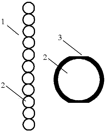
[0009] The swing rod 1 of the compound pendulum is composed of 99 metal rings 2 with a diameter of 1.2cm. The metal rings are symmetrically cut to a thickness of 1mm, so that the distance between the two cut surfaces 3 is 1cm. The metal rings are made of stainless steel or high hardness Aluminum alloy metal wire, the cross section of the metal wire is a circle with a diameter of 2mm. In order to ensure the symmetry of the swing bar, 99 rings are clamped with card slots to ensure that all rings are in close contact and all contact points are connected. The lines pass through the center of each ring, and then use the double-sided spot welding process to weld all the contact points of the rings.

[0010] The pendant of the compound pendulum is a stainless steel or high-hardness aluminum alloy cylinder with a diameter of 3-4mm.


PUM


Abstract

The invention discloses a no-twist compound pendulum consisting of an oscillating bar and a cylindrical pendant in ring connection, and relates to the field of manufacturing of a compound pendulum, particularly to the manufacturing of a no-twist compound pendulum applied to a gravitational acceleration experiment of a compound pendulum. The existing compound pendulum oscillating bar is in linear contact with the pendant, and thus twist happens frequently; and some patents adopt knife edge contact, and the durability of the pendant and the oscillating bar is low. In order to overcome the shortcomings of frequent twist of a common compound pendulum and easy damage in knife edge contact, the invention adopts a compound pendulum oscillating rod consisting of connected metal rings. According to the technical scheme, a plurality of rings with outer diameter of 1.2cm, which are composed of multiple stainless steel wires or high-hardness aluminum alloy wires with cross-sectional diameter of 2mm are symmetrically cut by 1mm thickness in a diameter direction, and the tangent plane contact of each ring is subjected to spot welding to form a compound pendulum oscillating bar. The no-twist compound pendulum has the following beneficial effects that point contact is realized between the compound pendulum oscillating bar and the pendant, and the twist of the compound pendulum oscillating bar can be effectively avoided; and the point contact is not knife edge contact, which ensures the peaceful coexistence of the oscillating bar and the pendant and improves the durability of the compound pendulum oscillating bar and the pendant.

Description

technical field [0001] The invention relates to the field of compound pendulum manufacture, in particular to the manufacture of a twist-free compound pendulum used in the experiment of measuring the acceleration of gravity with the compound pendulum. Background technique [0002] The currently used compound pendulum swing rod is in line contact with the pendant. Due to the unevenness of the pendant, the compound pendulum pendulum is prone to twisting, and it takes a long time to adjust the level of the pendant. There are patents that use knife-edge contact, and the knife-edge is point contact. , can effectively avoid twisting, but the sharper the knife edge is, the closer it is to point contact. [0003] The pendulum hole spacing of most laboratory pendulums is 2cm. Contents of the invention [0004] In order to overcome the deficiencies of ordinary compound pendulum being easy to twist and knife-edge contact being easily damaged, the present invention adopts a compound p...

Claims


Application Information

Patent Timeline
Patent Type & Authority Patents(China)
IPC IPC(8): G09B23/10
Inventor 胡再国何原王维果
Owner SICHUAN UNIV
Why Eureka
Try Eureka