Method and device for resource scheduling
A resource scheduling and scheduling queue technology, applied in wireless communication, electrical components, etc., can solve problems such as inability to guarantee service rate
- Summary
- Abstract
- Description
- Claims
- Application Information
AI Technical Summary
Problems solved by technology
Method used
Image
Examples
Embodiment 1
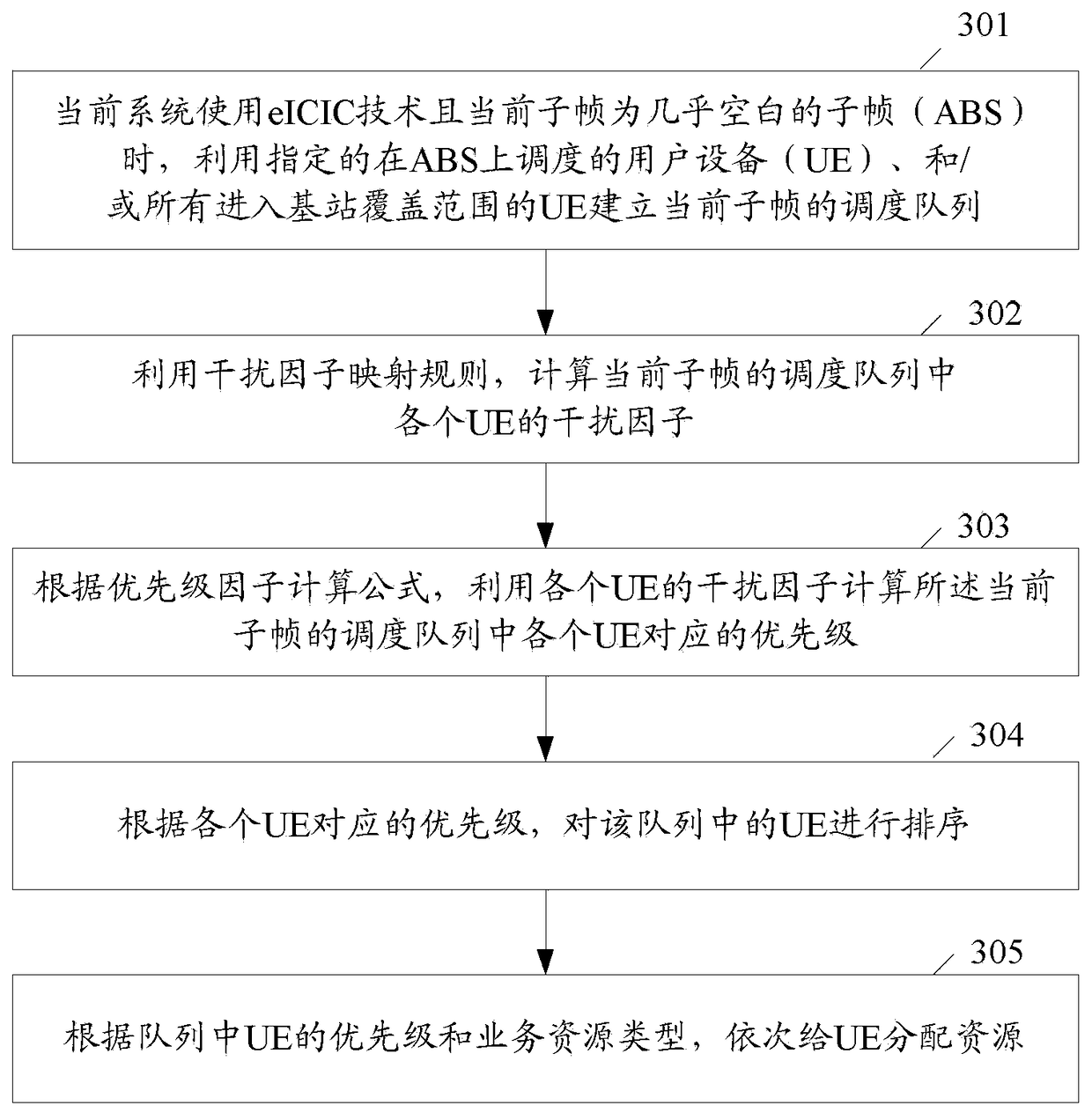
[0069] Step 301: When the current system uses eICIC technology and the current subframe is an ABS, use the specified UE scheduled on the ABS and / or all UEs entering the coverage of the base station to establish a scheduling queue for the current subframe.
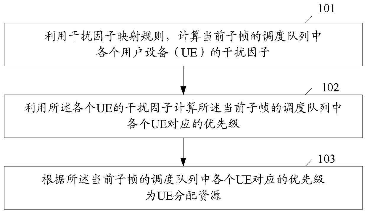
[0070] Step 302: Using the interference factor mapping rule, calculate the interference factor of each UE in the scheduling queue of the current subframe.
[0071] Assuming that a UE with an index of 10 is extracted from the scheduling queue of the current subframe, and the UE is designated to access the ABS, its BLER in the current subframe is obtained as 0.35, and the UE is obtained in The minimum BLER value of each schedulable subframe except the current subframe is 0.35, and the difference value is 0. According to the difference value, the corresponding interference factor is found from Table 1 to be FF Interference =64.
[0072] ΔBLER
>0.35
0.25~0.35
0.15~0.25
0.1~0.15
0.05~0.1
0~0.05
0 ...
Embodiment 2
[0080] Step 401: When the current system uses eICIC technology and the current subframe is non-ABS, use all UEs that enter the coverage of the base station except those designated for ABS subframe scheduling as UEs that need to be scheduled to establish a scheduling queue for the current subframe.
[0081] Step 402: Calculate the interference factor of each UE in the scheduling queue of the current subframe by using the interference factor mapping rule.
[0082] Assuming that the current subframe is subframe 2, and the UE whose ID (Index) is 12 is extracted from the scheduling queue of the current subframe, its BLER in the current subframe is obtained = 0.55, and Other schedulable subframes outside the subframe, that is, the minimum BLER on subframes 0, 1, 3, 4, 5, 6, 7, 8, and 9 is 0.1, and the difference is 0.45. According to the The difference is found from Table 1 and the corresponding interference factor is FF Interference =1.
[0083] Step 403: According to the priorit...
Embodiment 3
[0089] Step 501: The current system does not use the eICIC technology, and establishes a scheduling queue for the current subframe by taking all UEs that enter the coverage of the base station as UEs that need to be scheduled.
[0090] Step 502: Using the interference factor mapping rule, calculate the interference factor of each UE in the scheduling queue of the current subframe.
[0091] Assuming that the current subframe is subframe 0, and the UE whose ID (Index) is 5 is extracted from the scheduling queue of the current subframe, its BLER in the current subframe is obtained = 0.1, and the UE is Other schedulable subframes outside the subframe, that is, the minimum BLER on subframes 1, 2, 3, 4, 5, 6, 7, 8, and 9 is 0.05, and the difference is 0.05. According to the The difference is found from Table 1 and the corresponding interference factor is FF Interferenec =32.
[0092] Step 503: According to the priority factor calculation formula, use the interference factor of eac...
PUM
 Abstract
Description
Claims
Application Information
 - R&D
- Intellectual Property
- Life Sciences
- Materials
- Tech Scout
- Unparalleled Data Quality
- Higher Quality Content
- 60% Fewer Hallucinations
Browse by: Latest US Patents, China's latest patents, Technical Efficacy Thesaurus, Application Domain, Technology Topic, Popular Technical Reports.
© 2025 PatSnap. All rights reserved.Legal|Privacy policy|Modern Slavery Act Transparency Statement|Sitemap|About US| Contact US: help@patsnap.com


