
Clamping and positioning method for rear frame welding

A technology of clamping and positioning, rear frame, applied in welding equipment, auxiliary welding equipment, metal processing equipment, etc., can solve problems such as poor clamping and positioning, achieve good effect, high safety and practicability, and effective clamping The effect of positioning

Inactive Publication Date: 2014-12-10
CHENGDU RONGDE CONSTR LABOR
View PDF5 Cites 3 Cited by
  • Summary
  • Abstract
  • Description
  • Claims
  • Application Information

AI Technical Summary

Problems solved by technology

[0003] The invention provides a clamping and positioning method for rear frame welding, which is used to solve the problem of poor clamping and positioning during rear frame welding

Method used


Image

  • Clamping and positioning method for rear frame welding

Examples


Embodiment

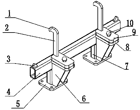
[0014] Such as figure 1 A clamping and positioning method for rear frame welding processing shown includes the following steps: (A) fixing the mounting plate on the turning frame fixing frame, and placing the rear frame on the end surface of the connecting plate; (B) clamping the plate The rear frame is positioned and clamped by the clamping structure, and the other end of the rear frame is fixed and locked with the fixed plate on the fixed frame, so that the fixed frame can be turned over arbitrarily, and the rear frame can be welded conveniently; the above steps Among them, the mounting plate 5 and the connecting plate 4 are connected by a support plate 7, the vertical side of the connecting plate 4 is connected with a fixed plate 8, the upper end surface of the fixed plate 8 is connected with a positioning plate 9 through a bolt 10, and the positioning plate 9 is connected The clamping plate 2, the upper part of the clamping plate 2 is bent to form a hook-shaped clamping st...


PUM


Abstract

The invention discloses a clamping and positioning method for rear frame welding. The method includes the following steps that first, an installing plate is fixed to a fixing frame of a turn-over frame, and a rear frame is placed on the upper end face of a connecting plate; second, the rear frame is positioned and clamped by a clamping plate through a clamping structure, the other end of the rear frame is fixed and fastened to a fixing disk on the fixing frame, and therefore the fixing frame can be turned over freely, and in other words, the rear frame can be welded conveniently. Due to the clamping and positioning method for rear frame welding, the rear frame can be effectively clamped and positioned, the effect is good, and safety performance and practicability are high.

Description

technical field [0001] The invention relates to a clamping and positioning device, in particular to a clamping and positioning method for rear frame welding. Background technique [0002] When processing the rear frame of the assembly machine, the rear frame needs to be welded in many places, and welding is inconvenient in many places, and because most of the rear frames are large in size and heavy in weight, it is necessary to fix the rear frame on a reversible On the turning frame, the turning frame is a device with a rotating shaft structure. The fixed frame connected to the rotating shaft is driven by the motor. The rear frame is fixed on the fixed frame, and each part of the rear frame is welded by the rotation of the fixed frame. It is necessary to set a clamping and positioning device to clamp and position the rear frame to ensure accurate positioning of the rear frame, firm clamping, and normal welding processing. Most of the current clamping and positioning devices...

Claims


Application Information

Patent Timeline
Patent Type & Authority Applications(China)
IPC IPC(8): B23K37/04
CPCB23K37/0435
Inventor 曾德明
Owner CHENGDU RONGDE CONSTR LABOR
Learn More