A kind of welding equipment and welding method of bimetallic band saw blade

A bimetal strip and welding equipment technology, applied in welding equipment, welding equipment, auxiliary welding equipment, etc., can solve the problems of tooling fixture wear, affecting product life, and welding seams are not easy to meet standards

Active Publication Date: 2020-05-15
PUTIAN HENGDA MACHINERY & ELECTRICITY IND
View PDF8 Cites 0 Cited by
  • Summary
  • Abstract
  • Description
  • Claims
  • Application Information

AI Technical Summary

Problems solved by technology

[0004] In the side butt welding of the strip and base material, due to the inaccurate positioning of the two materials, the weld between the two base materials is not easy to meet the standard. At the same time, due to the high hardness of the strip and base material, the corresponding tooling fixtures wear, further reducing the quality of the weld seam
The reduction of weld seam quality will lead to problems that affect the life of the product, such as sawtooth shedding of bimetallic saw blades

Method used


Image

  • A kind of welding equipment and welding method of bimetallic band saw blade
  • A kind of welding equipment and welding method of bimetallic band saw blade
  • A kind of welding equipment and welding method of bimetallic band saw blade

Examples


Embodiment Construction

[0043] Below in conjunction with accompanying drawing and embodiment of description, specific embodiment of the present invention is described in further detail:

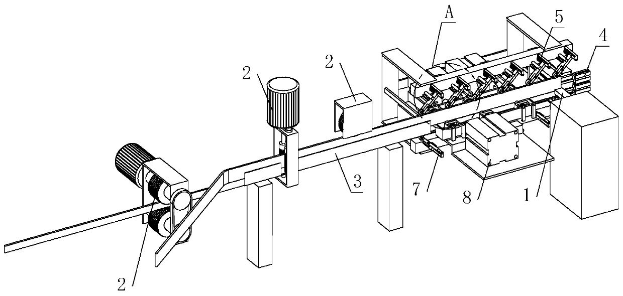
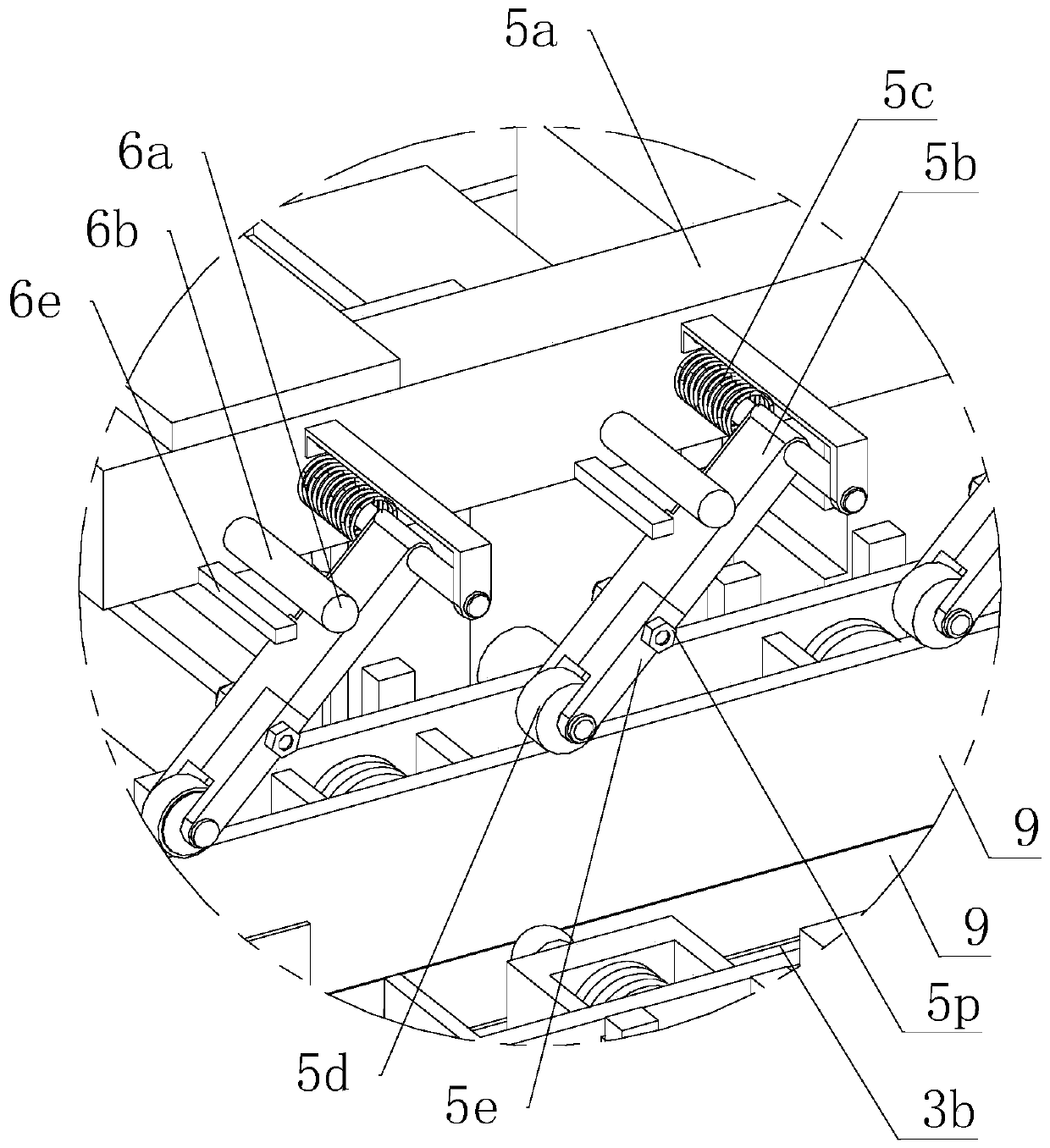
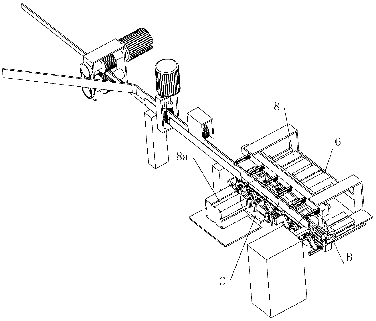
[0044] refer to Figure 1 to Figure 11 The welding equipment for a bimetallic band saw blade shown includes a laser generator 1, a base material feeding slide, a pre-welding position alignment device 4, a main controller, and an upper and lower clamping device 5 and a lower clamping device arranged symmetrically up and down 7. The laser generator 1 is arranged at the downstream end of the substrate feeding chute, and also corresponds to its front side, the upper gripper device 5 and the lower gripper device 7 are respectively located directly above and directly below the substrate feeding chute, and Both of them are located at the downstream end of the base material supply slideway. The back side of the base material supply slideway is provided with a power device for driving the upper clamp device 5 and the lower c...


PUM

PropertyMeasurementUnit
wavelengthaaaaaaaaaa

Abstract

The invention relates to the field of bimetallic saw strip machining, in particular to welding equipment and welding method for bimetallic band saw strips. The welding equipment comprises a laser generator, a base material supplying slide rail, a pre-welding position alignment device, a main controller, an upper fixture device and a lower fixture device, wherein the upper fixture device and the lower fixture device are symmetrically arranged up and down, the laser generator is arranged at the downstream end of the base material supplying slide rail, the upper fixture device and the lower fixture device are located above and below the base material supplying slide rail correspondingly, the back side of the base material supplying slide rail is provided with a power device, the front side and the back side of the base material supplying slide rail are each provided with one clamping device, and the pre-welding position alignment device can be movably arranged at the end portion of the downstream end of the base material supplying slide rail through an avoidance air cylinder and is further in electrical connection with the main controller. By means of the welding equipment and weldingmethod for the bimetallic band saw strips, two pre-welding base materials can be effectively clamped and positioned, and then the welding quality is improved, in addition, a rubber shaft sleeve and arubber sleeve which are in direct contact with the base materials can both be detachably arranged, and the fixture maintenance cost is greatly lowered.

Description

technical field [0001] The invention relates to the field of bimetallic saw blade processing, in particular to a welding device and a welding method for a bimetallic band saw blade. Background technique [0002] Bimetal band saw blade mainly refers to the metal cutting band saw blade whose tooth tip material is high-speed steel or other high-performance steel, and the saw band material is low-alloy spring steel. [0003] In the production and processing of bimetallic band saw blades, it needs to go through back material trimming → laser welding → bright annealing → welding seam flattening → leveling and straightening → fixed length preparation → milling teeth → splitting teeth → quenching and tempering → sandblasting → rolling Rolling and straightening → printing and antirust → coiling and packaging → fixed-length cutting tape → butt welding of the root tape → embedding of the root tape → packing of the root tape and other processes. , welded together with the substrate, wh...

Claims


Application Information

Patent Timeline
Patent Type & Authority Patents(China)
IPC IPC(8): B23K26/21B23K26/70B23K26/323B23K37/04
CPCB23K26/21B23K26/323B23K26/702B23K37/0426
Inventor 林君敏
Owner PUTIAN HENGDA MACHINERY & ELECTRICITY IND
Why Eureka
Try Eureka