
A spiral wire rotation wrench and design solution

A spiral wire and wrench technology, applied in the field of tightening tools, can solve the problems of high air pressure requirements, complex structure, large loss, etc., and achieve the effects of saving high-pressure air consumption, overcoming technical prejudice, and low noise

Active Publication Date: 2017-06-20
浙江舟水建设有限公司
View PDF9 Cites 1 Cited by
  • Summary
  • Abstract
  • Description
  • Claims
  • Application Information

AI Technical Summary

Problems solved by technology

[0002] The currently used jackhammer tools have a complex structure, heavy weight, high requirements on air pressure, high-pressure air consumption, large loss, and high noise during use.

Method used


Image

  • A spiral wire rotation wrench and design solution
  • A spiral wire rotation wrench and design solution

Examples


Embodiment Construction

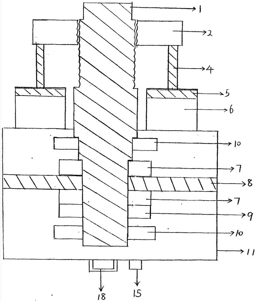
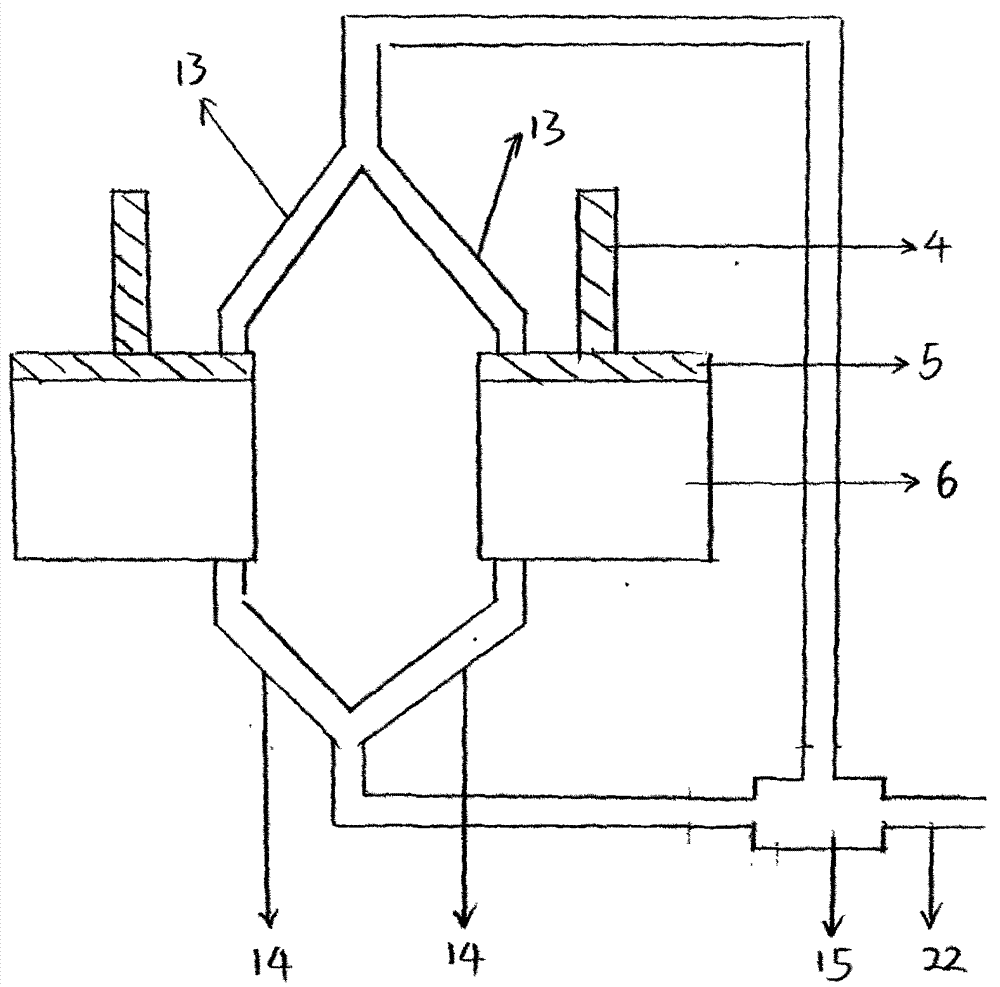
[0013] When the screw wrench completes the previous rotation and stops, the two pull rods (4) of the cylinder are in the extended state, install the required casing head on the upper end of the wrench pull rod (1), press the switch of the solenoid valve (15), and the cylinder ( 6) The pull rod (4) recovers quickly. Since the screw nut (2) is connected by the two pull rods, it cannot rotate. The screw nut moves down rapidly with the pull rod. At the same time as the screw nut moves down, the pull rod rotates accordingly, and the solenoid valve is pressed again. , the pull rod will be stretched out quickly, and the pull rod will rotate again. The two rotation directions of the pull rod are always opposite. When using it, select the direction to be rotated according to the needs.


PUM


Abstract

The invention belongs to the field of screwing tools, discloses a screw rod rotating spanner and a design scheme, and particularly relates to a jackhammer used for dissembling or assembling steel plate screws of automobile tires. A jackhammer tool used at present is complex in structure, large in gravity, high in air pressure requirement, large in high-pressure air consumption and loss and high in noise when used. According to the screw rod rotating spanner, the spanner is driven to rotate by rotation of a screw of a screw rod set; the lower end of the screw is located in a spanner body, the screw is fixed by a set of pressure bearings to move vertically, and the screw rod is prevented from moving in the tangential direction of the screw rod by a set of ball bearings; vertical rotating power of the spanner comes from vertical movement of a nut, pushed by a set of same air cylinders, of the screw rod, the air cylinders are fixed to the spanner body, the nut can not rotate and can only move vertically along with a pull rod to drive the screw to rotate in the telescoping process of the air cylinders, and when the pull rod rotates, the nut can be rotated by installing a sleeve head at the end of the pull rod.

Description

technical field [0001] The invention belongs to the field of tightening tools, in particular to a wind gun used for disassembling and installing steel plate screws of automobile tires. Background technique [0002] The currently used jackhammer tools have complex structures, heavy weight, high requirements on air pressure, high-pressure air consumption, large loss, and high noise during use. Contents of the invention [0003] The screw screw rotating wrench of the present invention is driven by the screw rotation of a group of screw screws. The lower end of the screw rod is located in the main body of the wrench, fixed by a group of pressure bearings to move up and down, and fixed by a group of ball bearings to prevent the screw rod from being tangential to the screw rod. Direction movement, up and down wrench rotation power comes from a group of the same cylinder to push the screw nut to move up and down, the cylinder and the wrench body are fixed, so the screw nut cannot...

Claims


Application Information

Patent Timeline
Patent Type & Authority Patents(China)
IPC IPC(8): B25B21/00
CPCB25B21/00
Inventor 陈安平朱光虞一平
Owner 浙江舟水建设有限公司
Learn More