Double-air-inlet centrifugal fan

A technology of centrifugal fan and double air intake, which is applied in the direction of mechanical equipment, machine/engine, liquid fuel engine, etc. It can solve the problems of uneven speed distribution of the impeller outlet, so as to overcome the uneven speed distribution, reduce the rotation noise, and increase the air volume Effect

Inactive Publication Date: 2014-12-10
GUANGDONG HISENSE HOME APPLIANCES CO LTD
View PDF7 Cites 24 Cited by
  • Summary
  • Abstract
  • Description
  • Claims
  • Application Information

AI Technical Summary

Problems solved by technology

[0007] In the above scheme, since the curved surface of the volute tongue is a concave curved surface, the frequency of the rotational noise generated by the impact and disturbance of the impeller outlet air on the volute tongue has a certain phase difference along the axial direction, which is beneficial to reduce the rotational noise. On the other hand, due to The contour line of the ...

Method used


Image

  • Double-air-inlet centrifugal fan
  • Double-air-inlet centrifugal fan
  • Double-air-inlet centrifugal fan

Examples


Embodiment 1

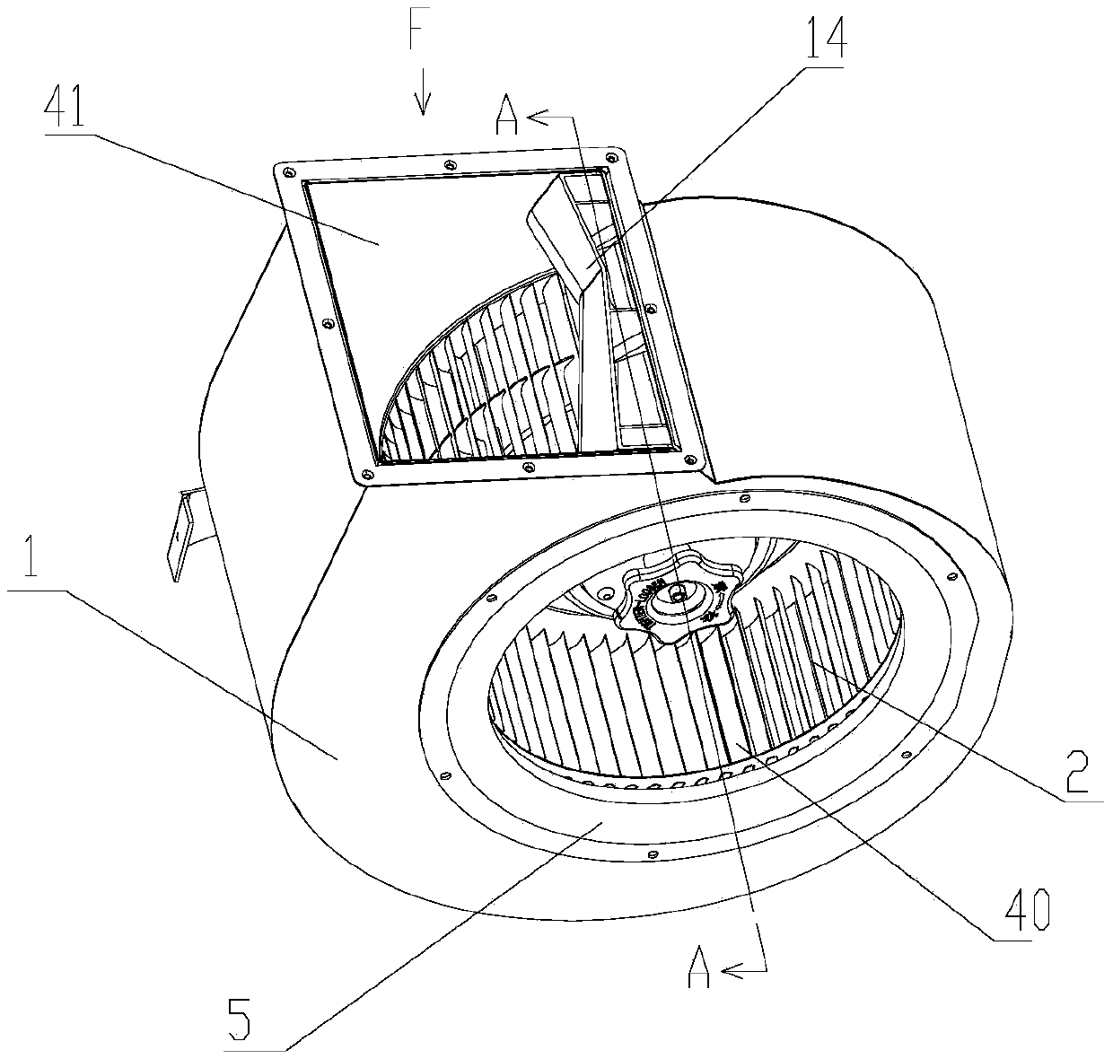
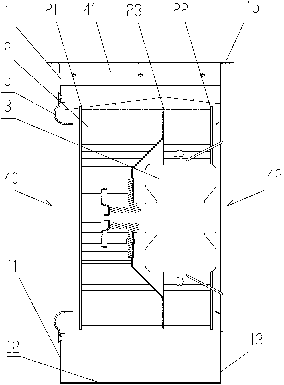
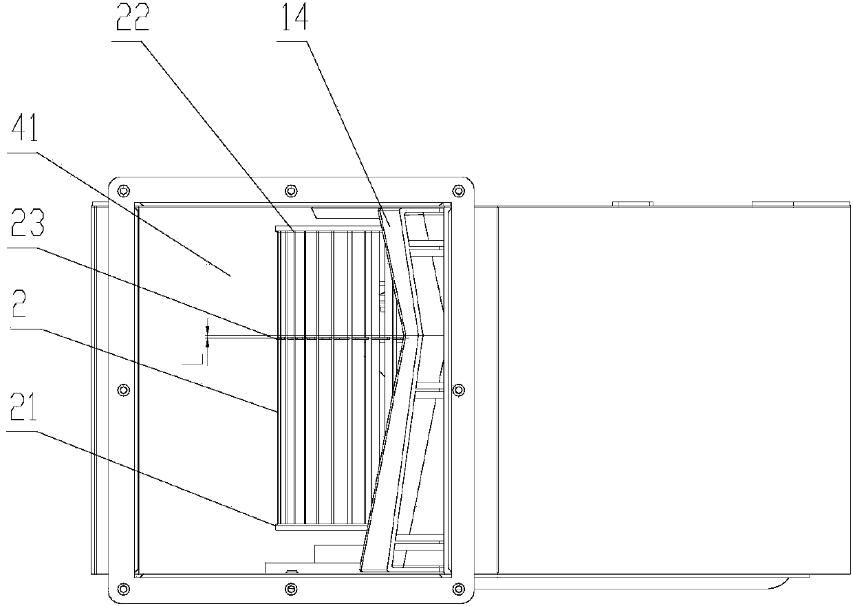
[0029] The double-inlet centrifugal fan of the present invention is as Figures 1 to 7 As shown, it includes a volute 1, a double air inlet impeller 2 and a motor 3, the double air inlet impeller 2 is installed on the rotating shaft of the motor 4 and placed in the volute 1, and the motor 4 is fixed 6 in the volute 1 by the motor fixing bracket , the volute 1 includes a front cover 11, a rear cover 13 and a volute coaming 12 placed between the front cover 11 and the rear cover 13, the front cover 11 is aligned with the double inlet impeller 2 The position is provided with a forward air passage 40, and the rear cover 13 is provided with a rear air inlet passage 42 at the position facing the double air inlet impellers 2. 12 is provided with an air outlet channel 41, and a volute flange 15 is provided at the air outlet port of the air outlet channel 41, and the front cover 11, the volute coaming 12 and the rear cover 13 are close to the air outlet of the air outlet channel 41. T...

Embodiment 2

[0034] The double-inlet centrifugal fan of this embodiment is similar to Embodiment 1, and the difference is that, as shown in 8 to 10, the above-mentioned volute tongue curved surface 142 is a concave arc-shaped curved surface, and the front edge of the volute tongue curved surface 142 is in contact with the fixed surface The distance of 144 is greater than the distance between the rear end edge of the curved surface 142 of the volute tongue and the fixed surface 144, that is, the height of the front end surface 141 of the volute tongue is greater than the height of the rear end surface 143 of the volute tongue, so that the curved surface 142 of the volute tongue is in a state of non-middle symmetry, which is beneficial to Improve the air volume, wind pressure and efficiency, and also achieve a better effect of reducing rotational noise.

[0035] The working principle of the double-inlet centrifugal fan in this embodiment is the same as that in Embodiment 1.


PUM


Abstract

The invention provides a double-air-inlet centrifugal fan which comprises a volute, double-air-inlet impellers and a motor. The double-air-inlet impellers are arranged on a rotating shaft of the motor and are arranged in the volute. The volute comprises a front cover plate, a rear cover plate and a volute coaming arranged between the front cover plate and the rear cover plate. The positions, aligned with the double-air-inlet impellers, of the front cover plate and the rear cover plate are provided with a front air-inlet channel and a rear air-inlet channel respectively. The volute coaming is provided with an air outlet channel. The position, corresponding to the air outlet channel, of the volute is provided with a volute tongue. The volute tongue comprises a volute tongue curved face, and the volute tongue curved face is located on one side of the air outlet channel and is an inwards-concave and asymmetric curved face. According to the double-air-inlet centrifugal fan, the inwards-concave and asymmetric curved face is adopted for the volute tongue curved face, on one hand, rotating noise can be reduced, on the other hand, a deep tongue form is adopted for the volute tongue contour line close to an impeller front end ring and an impeller rear end ring, a shallow tongue form is adopted for the volute tongue contour line close to an impeller middle disc, so that the problem caused by uneven outlet speed distribution of the impellers can be avoided, and thus air volume and air pressure are increased, and efficiency are improved easily.

Description

technical field [0001] The invention relates to a fan, in particular to a double-inlet centrifugal fan, which belongs to the improvement technology of the double-inlet centrifugal fan. Background technique [0002] At present, high-suction range hoods have become the mainstream of the industry. The double-inlet centrifugal fan has the characteristics of large flow coefficient, high pressure coefficient and compact structure, which meets the needs of high-suction range hoods. [0003] There is a tongue-shaped structure near the volute outlet of the centrifugal fan, called the volute tongue, which is used to divert the airflow directed to the volute outlet and prevent part of the gas from circulating in the volute. According to the length of the snail tongue and the radial distance from the snail tongue to the impeller, the snail tongue is divided into sharp tongue, deep tongue, shallow tongue and flat tongue. The sharp tongue is the longest and the radial distance from the i...

Claims


Application Information

Patent Timeline
IPC IPC(8): F04D29/42F04D29/66
Inventor 梁之博
Owner GUANGDONG HISENSE HOME APPLIANCES CO LTD
Why Eureka
Try Eureka