

Vertical lawn lamp
A lawn lamp and vertical technology, applied in the field of vertical lawn lamps, can solve the problems of insufficient ventilation of the heat dissipation plate, affecting the heat dissipation of the heat dissipation plate, etc., and achieve the effects of improving ventilation performance, improving heat dissipation efficiency, and being beneficial to production and use.
- Summary
- Abstract
- Description
- Claims
- Application Information
AI Technical Summary
Problems solved by technology
Method used
Image

Examples
Embodiment 1
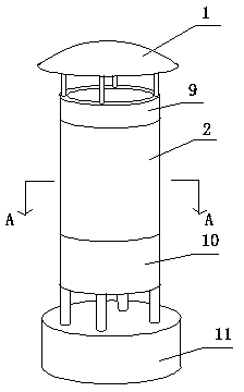
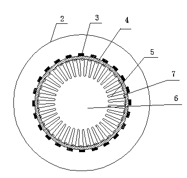
[0018] A kind of vertical lawn lamp, comprises lamp tube, tube cover 1, light-transmitting cover 2, LED light source assembly 3, radiator plate 4, as figure 1 with image 3 , the light transmission cover 2 is a cylindrical light transmission cover 2 made of transparent resin, the light transmission cover 2 is covered on the heat dissipation plate 4, the light transmission cover 2 and the heat dissipation plate 4 form a light source room, and the light source room is equipped with LED light source components 3. The LED light source assembly 3 includes a substrate and a number of LED light sources fixed on the substrate. The substrate is fixed on one side of the heat dissipation plate 4. The other side of the heat dissipation plate 4 is welded with a heat dissipation burr 5. The heat dissipation burr 5 is tapered, and the heat dissipation burr 5 The cross-sectional diameter gradually decreases from the welding end to the other end. The heat dissipation plate 4 is cylindrical. Th...
Embodiment 2
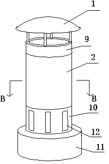
[0021] Embodiment 2 is basically the same structure as Embodiment 1, the difference is that the lamp tube includes an upper cylinder body 9 and a lower cylinder body 10, the upper cylinder body 9 is connected to the cylinder cover 1, the lower cylinder body 10 is sealed and connected to the cylinder seat 11, and the light-transmitting cover 2. The LED light source assembly 3 and the heat dissipation plate 4 are arranged between the upper cylinder 9 and the lower cylinder 10 , and the lower cylinder 10 is provided with a plurality of vents 12 communicating with the heat dissipation channels 6 . A heat dissipation umbrella group 8 is arranged between the adjacent heat dissipation burrs 5, and the heat dissipation umbrella group 8 is composed of several umbrella-shaped heat dissipation units connected in sequence.
[0022] The heat dissipation umbrella group 8 in the second embodiment greatly increases the heat dissipation area, and the heat dissipation effect is better. ...
PUM
 Abstract
Description
Claims
Application Information