Device and method for visually detecting front part of cutter head of cutter of shield tunneling machine

A shield machine tool and detection device technology, applied in the direction of measuring devices, material analysis through optical means, instruments, etc., can solve problems such as high risk, inability to sense, poor effect, etc., achieve important economic and social benefits, reduce The effect of maximizing engineering safety risks and operating benefits

Inactive Publication Date: 2014-12-10
CCCC TUNNEL ENG +2
View PDF7 Cites 12 Cited by
  • Summary
  • Abstract
  • Description
  • Claims
  • Application Information

AI Technical Summary

Problems solved by technology

Among the above methods, the method of opening the cabin for inspection is the most direct and effective, but it has a high risk, which may cause the collapse of the excavation surface, thereby affecting the safety of the surrounding buildings of the tunnel, and is expensive
The tool wear sensing device can only be installed on a small number of tools, and cannot sense the wear of other tools, and cannot detect partial wear and abnormal wear
Odor Additives Not Effective in EPB Shields and Slurry Shields
The tunneling parameter analysis method is to establish the total thrust, Empirical relationship between total torque and advance speed, which does not accurately predict tool wear

Method used


Image

  • Device and method for visually detecting front part of cutter head of cutter of shield tunneling machine
  • Device and method for visually detecting front part of cutter head of cutter of shield tunneling machine
  • Device and method for visually detecting front part of cutter head of cutter of shield tunneling machine

Examples


Embodiment Construction

[0024] The present invention will be further described below in conjunction with the accompanying drawings and specific embodiments.

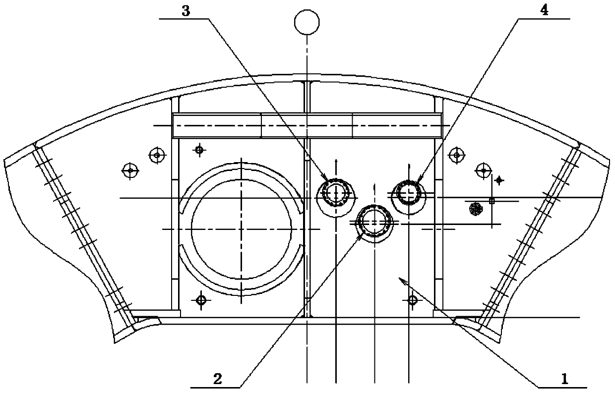
[0025] Such as figure 1In the described embodiment, a rear visual detection device for shield machine tool wear includes a camera device 2, an illumination device 3, a flushing device 4, a first propulsion device, a second propulsion device, a third propulsion device, data The acquisition device and the bubble chamber 1 of the shield machine. The camera device 2 includes a front-end camera for photographing the back of the cutterhead and a side camera for photographing the side of the cutterhead. Three round holes are arranged on the front wall of the shield machine bubble chamber 1 , the ball joints are welded with round holes and ball valves are respectively installed for connecting the camera device 2, the lighting device 3 and the flushing device 4, the first propulsion device is threaded with the camera device 2, the second propulsion devi...


PUM


Abstract

The invention discloses a device and a method for visually detecting the front part of a cutter head of a cutter of a shield tunneling machine, and the device and the method are safe, convenient, fast, economical and reliable. The device comprises a camera device, a lighting device, a washing device, a first propulsion device, a second propulsion device, a third propulsion device, a data acquisition device and a bubble cabin of the shield tunneling machine, wherein the camera device comprises a front end camera and a lateral camera; the front wall of the bubble cabin of the shield tunneling machine is provided with three circular holes; spherical hinges are welded in the circular holes, respectively, and ball valves for connecting the camera device, the lighting device and the washing device are arranged in the circular holes, respectively; the first propulsion device, the second propulsion device and the third propulsion device are connected with the camera device, the lighting device and the washing device by screw threads and are respectively connected with the front wall of the bubble cabin of the shield tunneling machine by the corresponding ball valve. The device and the method have the beneficial effects that large-area damage or unnecessary cabin opening inspection and cutter replacement, which are caused by the fact that the cutter is not replaced in time after being damaged, can be avoided, and the service life of the cutter is prolonged.

Description

technical field [0001] The invention relates to the related technical field of shield machine tool wear detection, in particular to a front-side visual detection device and method for shield machine tool cutter heads in tunnel shield construction. Background technique [0002] During shield tunneling, tool wear is unavoidable. After a small number of tools are worn out, if they are not detected and replaced in time, the wear rate of other tools on the cutter head will be greatly accelerated. However, tool replacement must be carried out under pressure, which is characterized by high safety risks, high costs, and long work periods. Therefore, man-made arbitrary and blind replacement of tools results in extended construction period, increased engineering costs and safety risks. The application of the traditional shield cutterhead wear monitoring system to this project will encounter shortcomings such as high safety risks, high economic costs, and long construction periods, a...

Claims


Application Information

Patent Timeline
Patent Type & Authority Applications(China)
IPC IPC(8): G01N21/84
Inventor 吴全立石振明石新栋姚占虎吕中海管圣功王善高张亚果张英明周骏杨红都苏延奇陈方伟
Owner CCCC TUNNEL ENG
Why Eureka
Try Eureka