Measurement method for differential antenna

An antenna measurement and differential technology, applied in the field of differential antenna measurement, can solve the problems of inability to achieve balanced antenna feeding, large errors, and inability to fully reflect the antenna state.

Active Publication Date: 2014-12-10
INST OF ELECTRONICS CHINESE ACAD OF SCI
View PDF7 Cites 14 Cited by
  • Summary
  • Abstract
  • Description
  • Claims
  • Application Information

AI Technical Summary

Problems solved by technology

Ordinary vector network analyzers and spectrum analyzers do not receive differential signals when measuring antenna characteristics, and only a coaxial cable is used to connect the antenna under test, which cannot achieve balanced feeding of the antenna; as mentioned above, conventional measurement methods mainly use bar Lun converts the differential port of the differential antenna into a single port, and then uses a vector network analyzer and other equipment for measurement
The antenna characteristics measured by this method are greatly affected by the balun, and cannot fully reflect the working state of the antenna. At the same time, the return loss and insertion loss of the balun itself are introduced, resulting in large errors, especially in the standing wave of the antenna voltage. In the ratio measurement, the error introduced by the balun cannot be eliminated through post-data processing

Method used


Image

  • Measurement method for differential antenna
  • Measurement method for differential antenna
  • Measurement method for differential antenna

Examples


Embodiment Construction

[0059] The present invention will be described in detail below with reference to the accompanying drawings and examples.

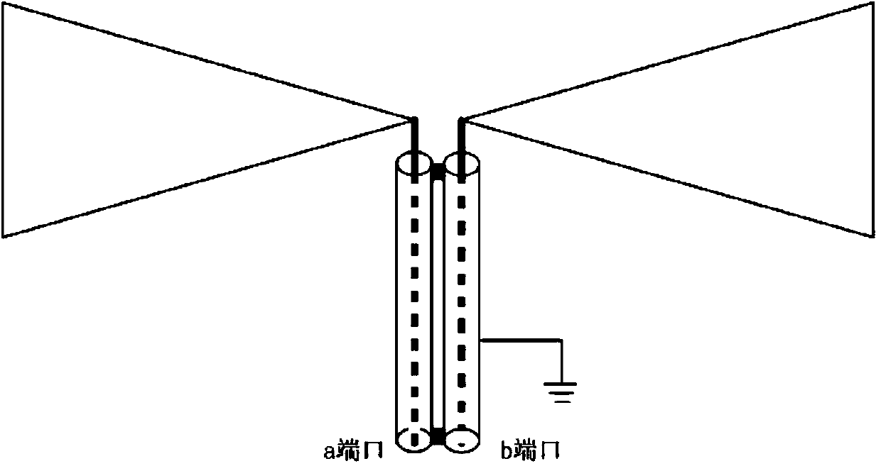
[0060] Such as figure 1 As shown, is a schematic diagram of the structure of the differential antenna 1 to be tested, and the feeding end of the differential antenna 1 is composed of a differential port a and a differential port b.

[0061] (1) The isolation test method of differential antenna 1 is as follows:

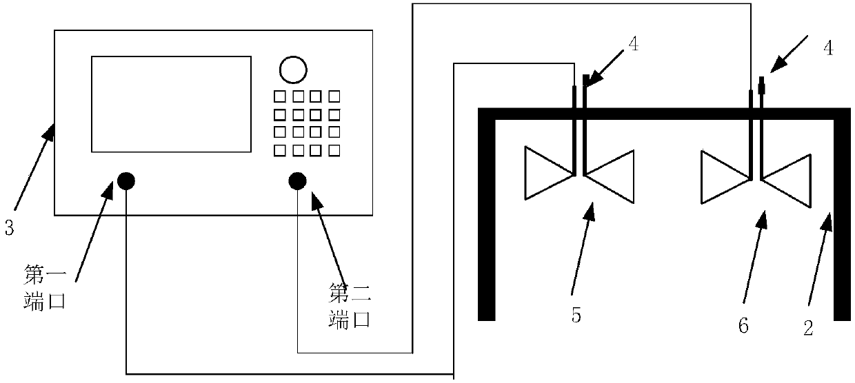
[0062] Such as image 3 As shown, it is a device diagram of the isolation test method of the differential antenna 1, including a vector network analyzer 3, a balun 7, a matching load 4, a transmitting antenna 5 and a receiving antenna 6. Among them, the balun 7 has the functions of unbalanced-balanced transformation and impedance transformation, and is used to realize the matching between the output port of the vector network analyzer 3 and the differential port input by the transmitting antenna 5; the impedance of the matching load 4 is consiste...


PUM


Abstract

The invention discloses a measurement method for a differential antenna, wherein use of a Balun is reduced to the greatest extent, a comprehensive measurement is carried out on Balun characteristics in the case that the Balun needs to be used, and a measurement error introduced by the Balun is eliminated in the subsequent data processing, thus the measurement is more accurate; the measurement method is higher in accuracy compared with the traditional measurement method, low in introduction error, and capable of being widely applied to a measurement for the differential antenna; a matching load is reasonably used during the measurement process, thus the adverse effect of a suspended antenna arm on the characteristics of the antenna during the single-end measurement for the differential antenna is reduced, and the impedance characteristic and the radiation characteristic of the antenna are really reflected in a manner of power synthesis; the measurement for the differential antenna by virtue of a coaxial cable is realized. The measurement method adequately considers the application environment of the antenna, all the measurements simulate the real environment of the antenna, and the obtained measurement result is capable of keeping consistent with the characteristics during the applications of the antenna.

Description

technical field [0001] The invention relates to the technical field of antenna measurement, in particular to a differential antenna measurement method. Background technique [0002] The electrical parameters of the antenna are important technical indicators in the antenna design and an important basis for the design of the electronic system; the electrical parameters of the antenna mainly include voltage standing wave ratio, isolation, gain, and pattern. The voltage standing wave ratio parameter reflects the reflection characteristics of the antenna input port and defines the impedance bandwidth of the antenna; the isolation parameter reflects the coupling strength between the transmitting and receiving antennas; the gain and pattern parameters together reflect the radiation characteristics of the antenna. The voltage standing wave ratio and isolation of the antenna are usually measured with a vector network analyzer, and the gain and pattern of the antenna are usually measu...

Claims


Application Information

Patent Timeline
Patent Type & Authority Applications(China)
IPC IPC(8): G01R27/28G01R27/06
Inventor 卢伟纪奕才方广有
Owner INST OF ELECTRONICS CHINESE ACAD OF SCI
Why Eureka
Try Eureka