
X type folding bracket

A technology of folding brackets and support rod components, which is applied to the support of musical instruments, expandable cabinets, instruments, etc., can solve the problems of inconvenient operation and achieve the effect of convenient use and adjustment

Active Publication Date: 2014-12-10
NINGBO SOUNDKING ELECTRONICS
View PDF7 Cites 14 Cited by
  • Summary
  • Abstract
  • Description
  • Claims
  • Application Information

AI Technical Summary

Problems solved by technology

[0003] For example, the utility model announcement of Chinese Patent No. 201020026750.3 discloses a support structure for an electronic piano frame, which adopts the second support rod to be set as a rod body formed by connecting the upper rod body and the lower rod body through a positioning plate, and makes the rod body pass through the positioning plate It is hinged on the same plane with the first support rod, which makes the opening and closing of the piano frame and the adjustment of the use height more convenient and quick; The cooperation between the positioning piece and the toothed groove adjusts the angle of the first support rod and the second support rod when they are staggered, so as to adjust the overall height. When the two support rods are folded, they are locked and fixed by the positioning piece and the toothed groove; however , when the two support rods are unfolded or folded, it is necessary to repeatedly operate the positioning piece to achieve the corresponding function, and once the height adjustment is not in place, it is necessary to operate the positioning piece multiple times to adjust the height of the piano stand to a suitable position, which is not convenient enough to operate

Method used

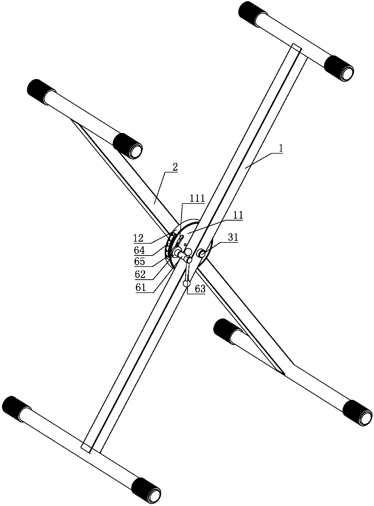
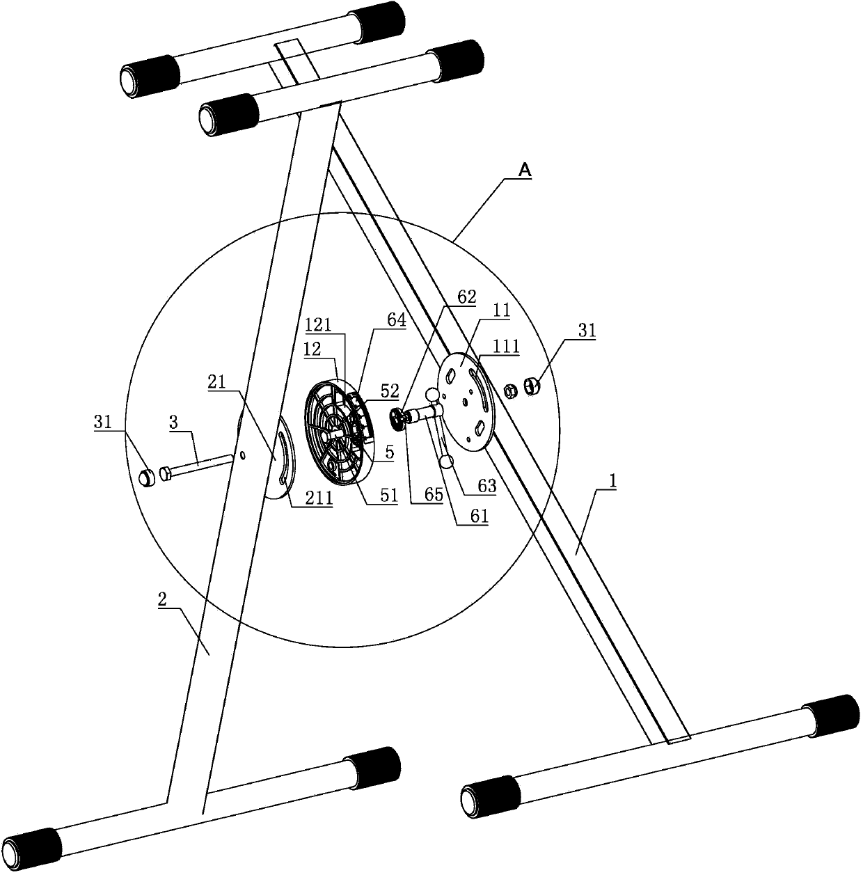
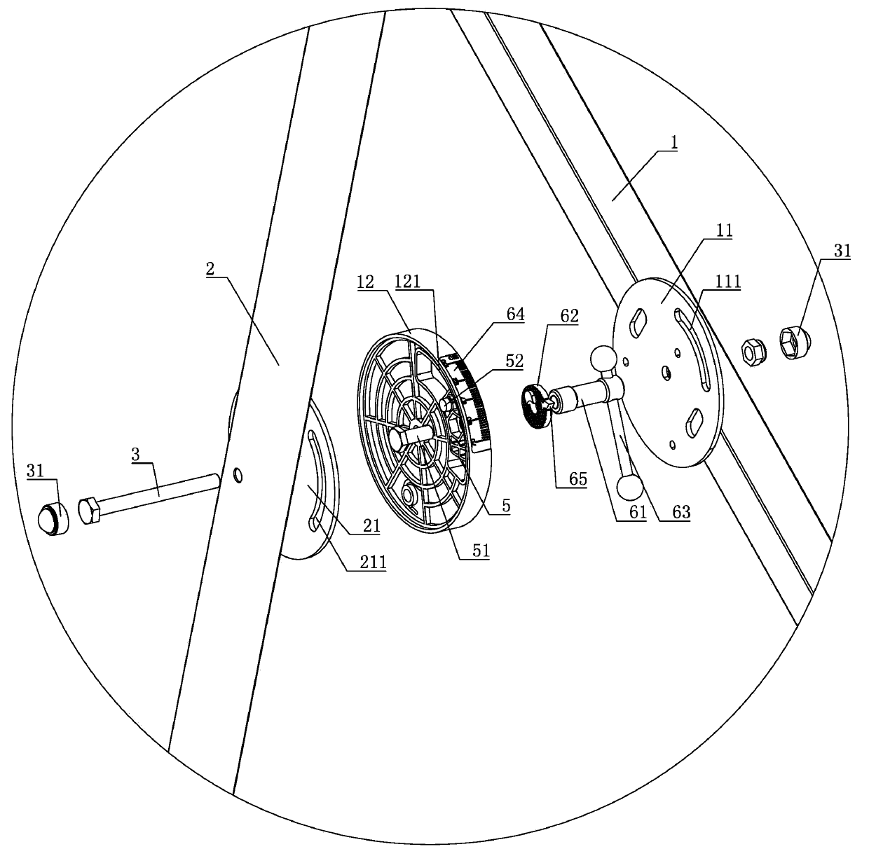

Image

  • X type folding bracket
  • X type folding bracket
  • X type folding bracket

Examples


Embodiment Construction

[0015] The present invention will be further described in detail below in conjunction with the accompanying drawings and embodiments.

[0016] An x-shaped folding bracket, including a first support rod assembly 1 and a second support rod assembly 2, the first support rod assembly 1 and the second support rod assembly 2 are pivoted together by a pin shaft 3, the first support rod assembly 1 A height adjustment device is provided at the shaft joint with the second support rod assembly 2, and the height adjustment device includes a first turntable 11 welded and fixed on the first support rod assembly 1, a second turntable 11 welded and fixed on the second support rod assembly 2 The rotating disk 21 and the fixed disk 12 located between the first rotating disk 11 and the second rotating disk 21, the fixed disk 12 is fixedly connected with the first rotating disk 11, the first rotating disk 11 is provided with a first round hole (not shown in the figure), the second The second turn...


PUM


Abstract

The invention discloses an X type folding bracket. The X type folding bracket comprises a first supporting rod assembly and a second supporting rod assembly which are integrally shafted through a hinge pin; a height adjusting device is arranged at a part in which the first supporting rod assembly and the second supporting rod assembly are shafted. The X type folding bracket is characterized in that the height adjusting device comprises a first rotating plate, a second rotating plate and a fixed plate; an arc-shaped sliding groove is arranged in the fixed plate; an arc-shaped adjusting groove is arranged in the first rotating plate; an arc-shaped limiting groove in which a limiting block is arranged is formed in the second rotating plate; an adjusting pin and a limiting pin are fixedly arranged on the limiting block, wherein the adjusting pin passes through the arc-shaped adjusting groove, and while the limiting pin extends into the arc-shaped limiting groove; a positioning device is arranged at the end part of the adjusting pin. The X type folding bracket has the advantages that the use height of the X type folding bracket can be adjusted by adjusting the position of the limiting block in the arc-shaped sliding groove through the positioning device; in addition, the X type folding bracket can be folded without operating the positioning device, so that the use and adjusting are convenient.

Description

technical field [0001] The invention relates to a bracket structure, in particular to an x-shaped folding bracket. Background technique [0002] Because of its flexible height adjustment, the x-shaped folding bracket is convenient for the storage of the supporting structure after folding. It is usually used as a supporting frame structure and widely used in devices that need to be accessed and stored, such as piano frames, folding desk frames, or folding chairs. [0003] For example, the utility model announcement of Chinese Patent No. 201020026750.3 discloses a support structure for an electronic piano frame, which adopts the second support rod to be set as a rod body formed by connecting the upper rod body and the lower rod body through a positioning plate, and makes the rod body pass through the positioning plate It is hinged on the same plane with the first support rod, which makes the opening and closing of the piano frame and the adjustment of the use height more conve...

Claims


Application Information

Patent Timeline
IPC IPC(8): G10G5/00A47B45/00A47B46/00
Inventor 熊齐军
Owner NINGBO SOUNDKING ELECTRONICS
Learn More