Cutting device for building steel production
A cutting device and steel technology, applied in positioning devices, large fixed members, clamping, etc., can solve the problems of difficult adjustment and fixing of the height of the clamping table, inability to realize inclined cutting of building steel, poor clamping stability, etc. , to achieve the effects of improving stability, facilitating production and processing, and ensuring accuracy
- Summary
- Abstract
- Description
- Claims
- Application Information
AI Technical Summary
Problems solved by technology
Method used
Image
Examples
Embodiment 1
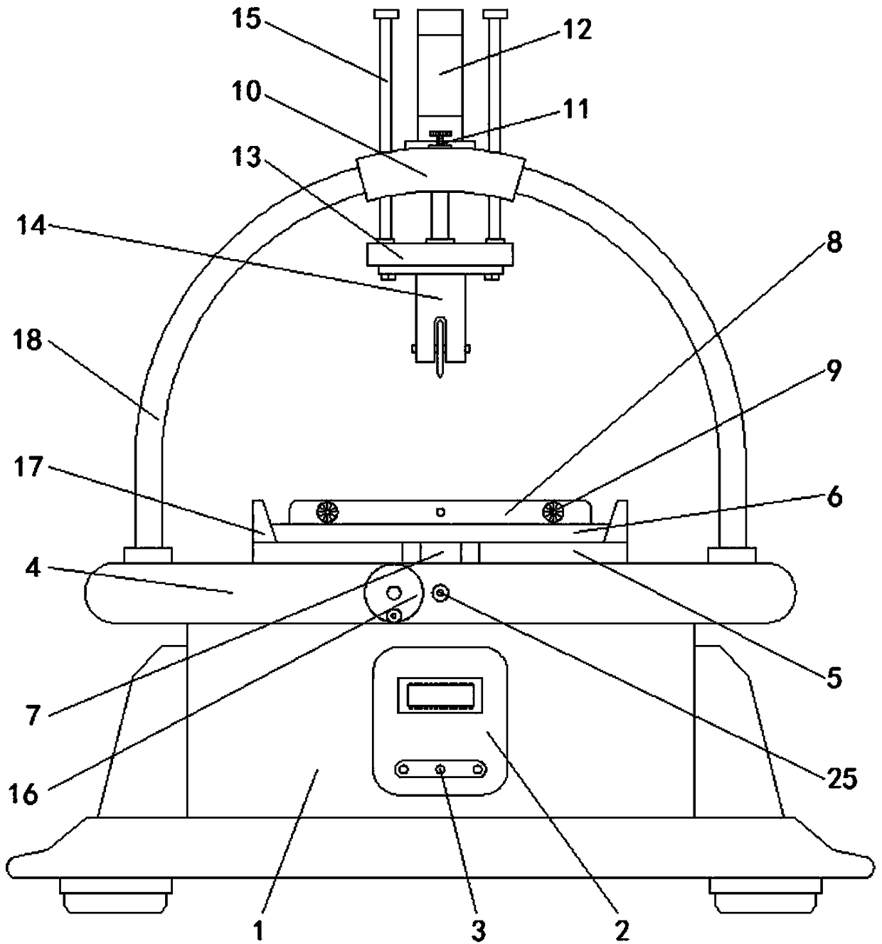
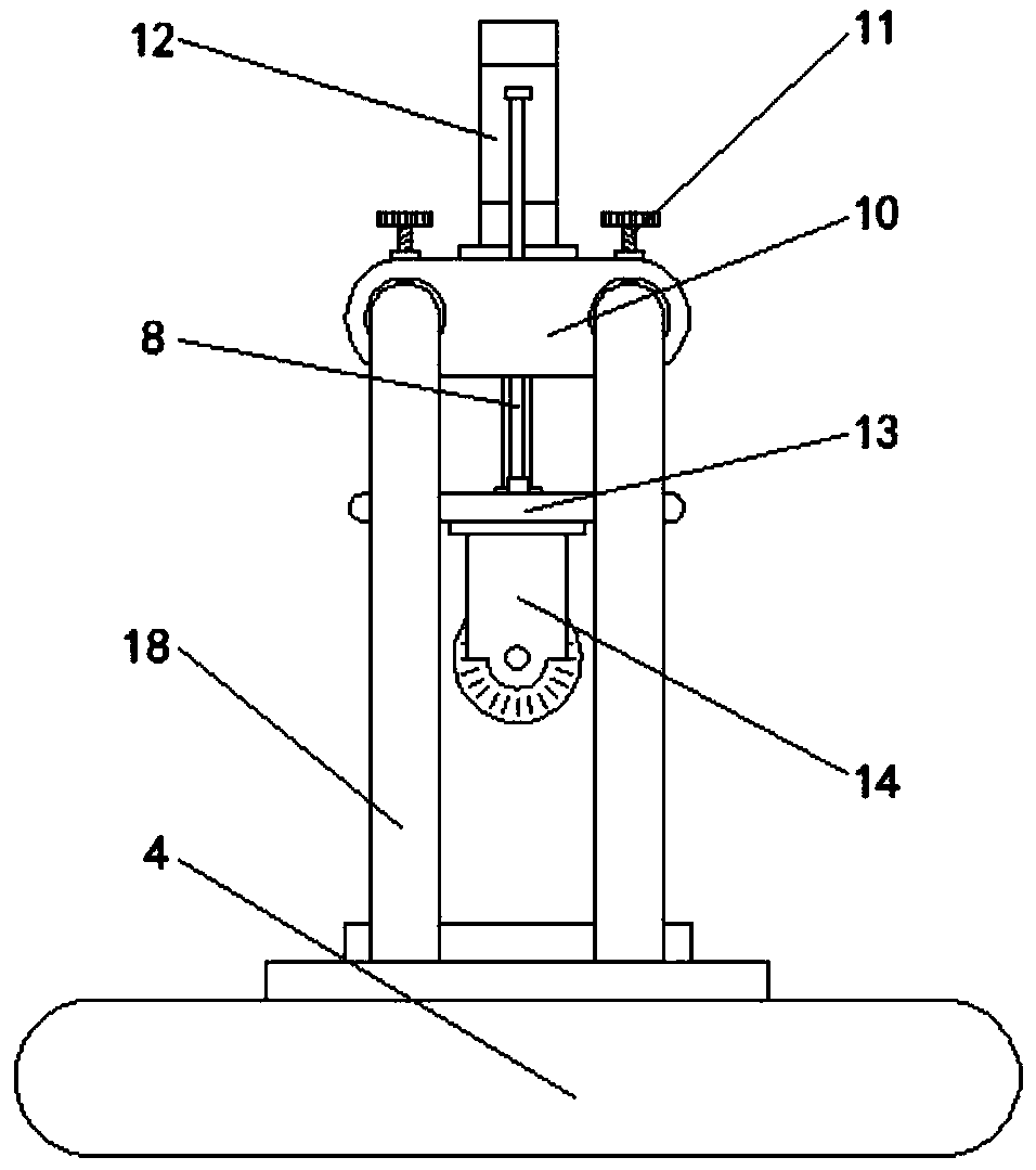
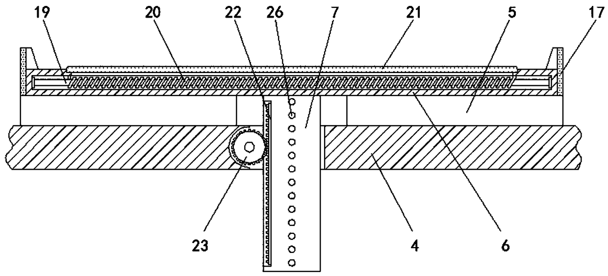
[0024] Embodiment one, with reference to Figure 1-4 , a cutting device for building steel production, including a base 1 and a cutting machine 14, the top of the base 1 is welded with a workbench 4, the top of the workbench 4 is symmetrically welded with a spacer 5, and the center of the top of the spacer 5 is provided with a Clamping platform 6, the inner side of clamping platform 6 is horizontally welded with soft iron core 19, and the outside of soft iron core 19 is wound with energized coil 20, and the top center of clamping platform 6 is embedded with rubber partition 21, rubber partition The setting of the plate 21 is convenient for the electromagnetic and magnetic treatment of the construction steel, and at the same time improves the stability of the placement of the construction steel. The center of the bottom of the clamping table 6 is welded with a lifting block 7 that runs through the workbench 4, and one side of the lifting block 7 is welded There is a rack 22, an...
Embodiment 2
[0025] Embodiment two, refer to figure 1 , image 3 and Figure 4 , the top of pad 5 is positioned at the four corners of clamping platform 6 and is welded with limit plate 17, and the top of clamping platform 6 is welded with splint 8 symmetrically about the vertical center line of clamping platform 6, and the inside of two clamping plates 8 is about The vertical center line of splint 8 is symmetrically screwed and connected with adjusting studs 9, and one end of two adjusting studs 9 close to clamping platform 6 is connected with clamping block 24 through rotating shaft, and the setting of limit plate 17 can prevent clamping The shaking in the horizontal direction of the platform 6 facilitates the adjustment of the vertical direction of the clamping platform 6, thereby improving the stability of the adjustment movement of the clamping platform 6. The setting of the clamping block 24 facilitates the fixing process of the building steel in the horizontal direction, thereby im...
Embodiment 3
[0026] Embodiment three, refer to image 3 and Figure 4 , the soft iron cores 19 are provided with multiple groups, and the multiple groups of soft iron cores 19 are distributed horizontally, the limit holes 26 are provided with multiple groups, and the multiple sets of limit holes 26 are vertically equidistantly distributed, the slide rails 18 The vertical section of the vertical section is a semi-arc structure, and the setting of multiple sets of soft iron cores 19 can improve the magnetic attraction force of the clamping table 6, thereby improving the stability of the electromagnetic magnetic attraction fixation, and the setting of multiple sets of limit holes 26 facilitates The adjustment and fixing process of the vertical direction of the lifting block 7 and the slide rail 18 in a semi-arc structure are convenient for the adjustment process of different inclination angles of the slide block 10, so that the cutting process of the specified inclination angle of the cutting...
PUM
 Abstract
Description
Claims
Application Information
 - R&D
- Intellectual Property
- Life Sciences
- Materials
- Tech Scout
- Unparalleled Data Quality
- Higher Quality Content
- 60% Fewer Hallucinations
Browse by: Latest US Patents, China's latest patents, Technical Efficacy Thesaurus, Application Domain, Technology Topic, Popular Technical Reports.
© 2025 PatSnap. All rights reserved.Legal|Privacy policy|Modern Slavery Act Transparency Statement|Sitemap|About US| Contact US: help@patsnap.com


