
Wireless charging method and device for electronic equipment, electronic equipment

A technology of wireless charging equipment and electronic equipment, applied in the field of communication, can solve problems such as loss, waste of time, and failure to guarantee the energy conversion efficiency of the launch board

Active Publication Date: 2017-01-11
NANJING ZHONGXING SOFTWARE
View PDF5 Cites 0 Cited by
  • Summary
  • Abstract
  • Description
  • Claims
  • Application Information

AI Technical Summary

Problems solved by technology

[0006] For the wireless charging technology of the magnetic resonance method, although the transmitting end and the receiving end of the charging can be located at a relatively far and relatively free position of about 50cm, but because the magnetic resonance field transmitting end is in the form of a plurality of continuous emitting plate arrays, it is fixed and dead. The receiving board of electronic equipment cannot guarantee that it is exactly on a specific emitting board to achieve the maximum energy conversion efficiency, and there are also loss factors
[0007] Aiming at the problems of wasting time and poor user experience caused by adjusting electronic devices back and forth during the wireless charging process of electronic devices that need to be charged in the related art, no effective solution has been proposed yet.

Method used


Image

  • Wireless charging method and device for electronic equipment, electronic equipment
  • Wireless charging method and device for electronic equipment, electronic equipment
  • Wireless charging method and device for electronic equipment, electronic equipment

Examples


Embodiment Construction

[0037] Hereinafter, the present invention will be described in detail with reference to the accompanying drawings and in conjunction with embodiments. It should be noted that the embodiments in the present application and the features of the embodiments may be combined with each other in the case of no conflict.

[0038] Other features and advantages of the present invention will be set forth in the description which follows, and, where appropriate, will be apparent from the description, or may be learned by practice of the invention. The objectives and other advantages of the invention may be realized and attained by the structure particularly pointed out in the written description, claims, and drawings.

[0039] Embodiments of the present invention provide a wireless charging method for an electronic device, figure 1 is a flowchart of a wireless charging method for an electronic device according to an embodiment of the present invention, such as figure 1 As shown, the meth...


PUM


Abstract

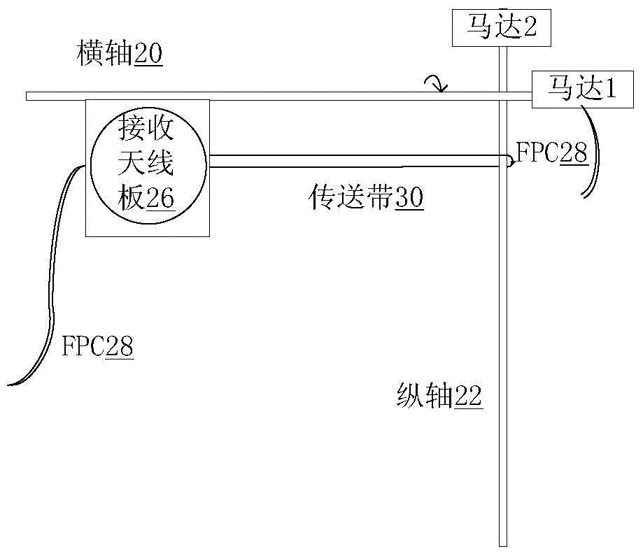
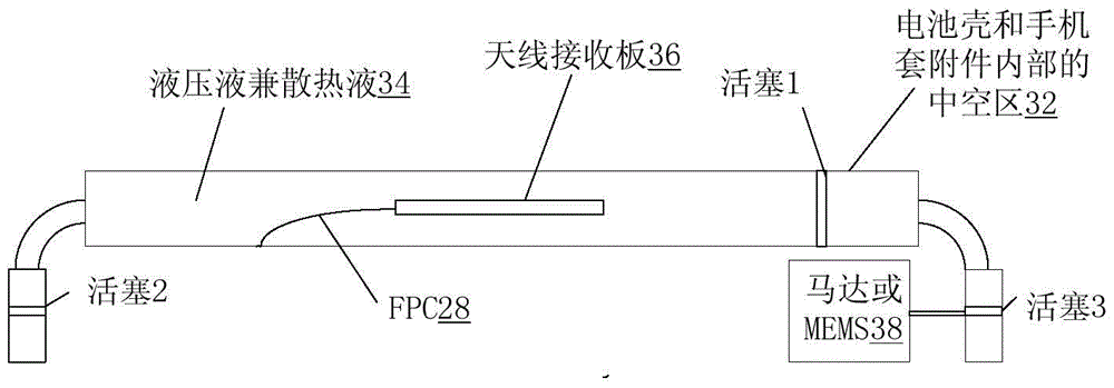
The present invention provides a wireless charging method and device for electronic equipment, and electronic equipment, wherein the wireless charging method includes: detecting the environmental parameters emitted by the wireless charging equipment; moving the receiving antenna in the electronic equipment according to the environmental parameters to a designated position, wherein the charging efficiency of charging the electronic device at the designated position is higher than that of charging at other positions. The above-mentioned technical solution provided by the present invention solves the problems of wasted time and poor user experience caused by adjusting the electronic device back and forth during the wireless charging process of the electronic device that needs to be charged in the related art, and realizes the free positioning of the antenna position. It greatly reduces the matching time between the electronic device and the wireless power supply device during the wireless charging process.

Description

technical field [0001] The present invention relates to the communication field, and more specifically, to a wireless charging method and device for electronic equipment, and electronic equipment. Background technique [0002] Because wireless charging technology is not limited by wired charging cables, it has been widely used in electronic devices, especially portable electronic devices (mobile terminals, tablet computers, etc.), and has broad development prospects. [0003] The wireless charging receiver on the electronic device side exchanges power with the transmitter of the wireless charging device at close range, whether it is the wireless charging standard Qi (Wireless Power Consortium, WPC / Qi for short) launched by the Wireless Charging Alliance in the form of electromagnetic induction, developed by Powermat The wireless charging technology (Power Matters Alliance, referred to as PMA) technology initiated by the company is also a form of magnetic resonance created by...

Claims


Application Information

Patent Timeline
Patent Type & Authority Patents(China)
IPC IPC(8): H02J7/00H02J50/20H02J50/90
CPCH02J7/0042H02J50/90H02J50/10G01B7/003H02J50/12H02J50/005
Inventor 张永亮
Owner NANJING ZHONGXING SOFTWARE
Learn More