Disc brake

A technology of disc brakes and brake blocks, which is applied in the direction of brakes, brake types, axial brakes, etc., and can solve problems such as impossibility

Inactive Publication Date: 2014-12-10
TOYOTA JIDOSHA KK
View PDF10 Cites 13 Cited by
  • Summary
  • Abstract
  • Description
  • Claims
  • Application Information

AI Technical Summary

Problems solved by technology

In addition, there is a problem that a structure that can generate a sufficient magnetic force (a force that separates the pressure piece from the brake disc) cannot be realized in a very limited space inside the cylinder

Method used


Image

  • Disc brake
  • Disc brake
  • Disc brake

Examples


Embodiment Construction

[0027] Hereinafter, the best mode for carrying out the present invention will be described with reference to the drawings.

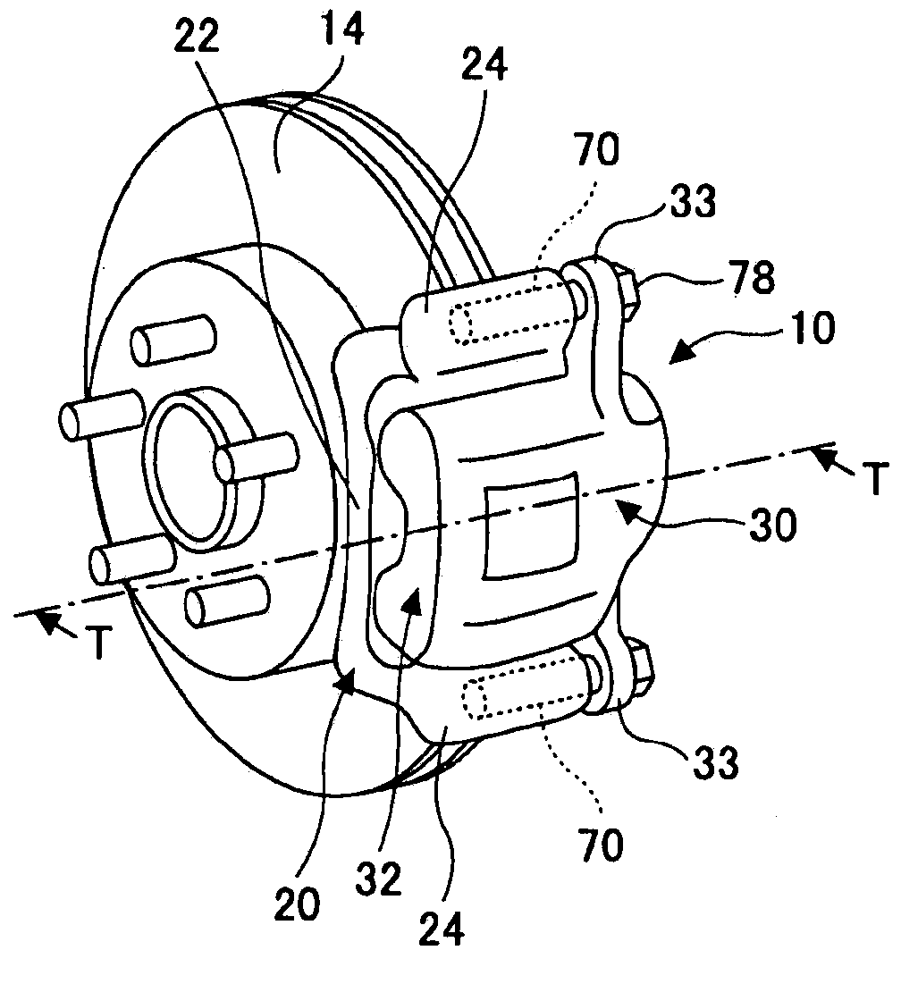
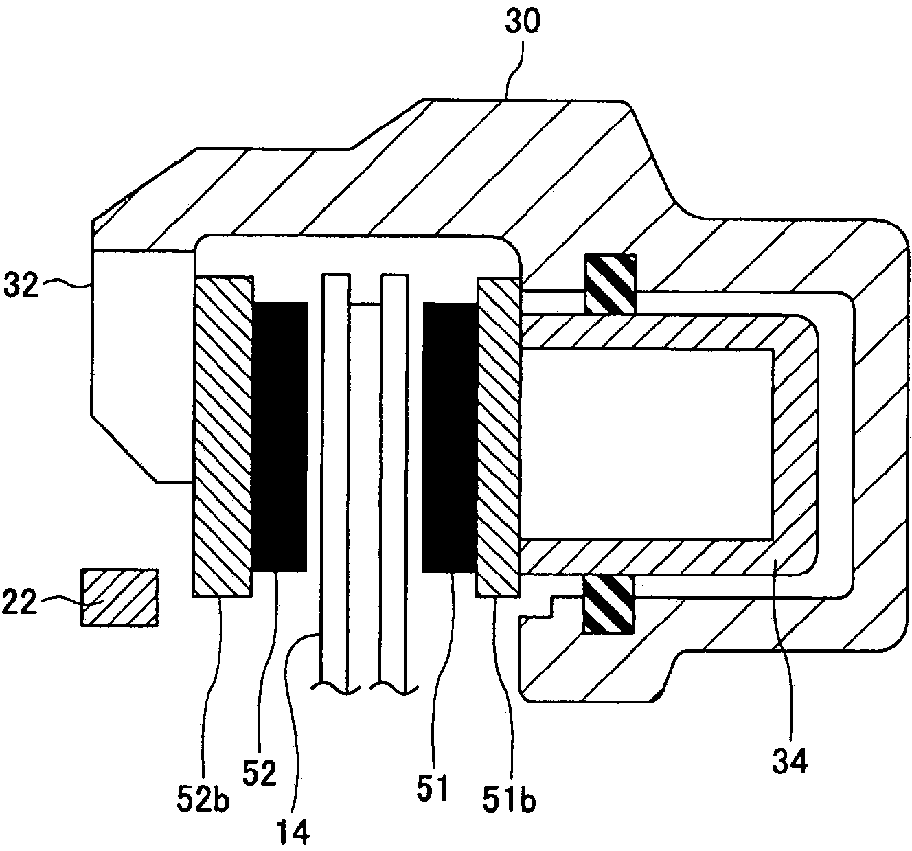
[0028] figure 1 is a perspective view showing an example of the disc brake 10, figure 2 is to mean along figure 1 A cross-sectional view of the main part of the disc brake 10 on the line T-T.

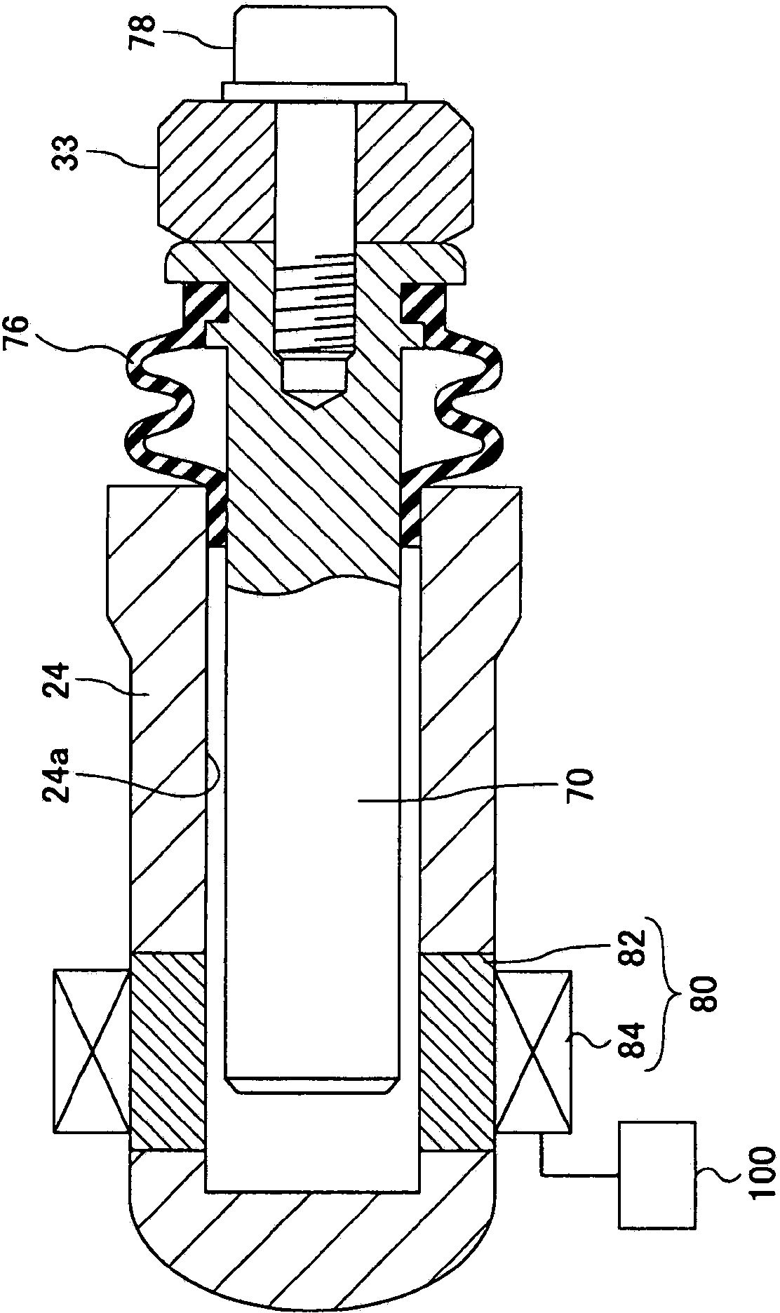
[0029] The disc brake 10 has a mounting bracket 20 (hereinafter simply referred to as "mounting bracket 20"). The mounting bracket 20 is fixed to the vehicle body (for example, a knuckle of a suspension). A cylinder main body (caliper) 30 (hereinafter simply referred to as “cylinder block 30 ”) is attached to the mounting bracket 20 via slide pins 70 . In addition, brake pads (inner pad 51 and outer pad 52 ) are supported on the mounting frame 20 . The inner pad 51 and the outer pad 52 are disposed so as to sandwich the disc rotor 14 rotating together with the wheel from the inside and outside of the vehicle.

[0030] Such as figure 1 As shown, the mount...


PUM


Abstract

In one embodiment, this disc brake, which is such that a caliper is supported with a slide pin therebetween by a mounting bracket affixed to a non-rotating section of a vehicle, is provided with a magnet that is provided to the slide pin and draws the slide pin in the axial direction in a manner so that the a brake pad separates from a disc rotor. In a separate embodiment, the disc brake, which is such that a caliper is supported with a slide pin therebetween by a mounting bracket affixed to a non-rotating section of a vehicle, is provided with: a magnetic body section at the backing plate of the brake pad; and a magnet provided to a position facing the magnetic body section in the direction of vehicle width.

Description

technical field [0001] The present invention relates to a disc brake in which a caliper is supported via a slide pin on a mounting bracket fixed to a non-rotating portion of a vehicle. Background technique [0002] In the past, disc brakes are known which have magnets installed oppositely on the inner sides of two pressing blocks (rear plates) and a solenoid installed between these magnets, and after braking, the The solenoid is energized to release the pressure piece from the disc (for example, refer to Patent Document 1). [0003] prior art literature [0004] patent documents [0005] Patent Document 1: Japanese Patent Application Publication No. 3-124032 ( figure 2 ) Contents of the invention [0006] The problem to be solved by the invention [0007] However, the structure described in Patent Document 1 has the problem that in order to ensure a space for arranging magnets and solenoids in the cylinder (outside in the radial direction of the brake rotor), the cyli...

Claims


Application Information

Patent Timeline
Patent Type & Authority Applications(China)
IPC IPC(8): F16D65/18F16D65/14
CPCF16D2121/20F16D55/22655F16D65/14F16D55/2265F16D65/18F16D2129/06F16D2121/22F16D55/226F16D65/092F16D55/227F16D2055/0029F16D2129/08B60T1/065
Inventor 横山智宏今野维薰佐藤浩显桑鹤清志石田贵洋
Owner TOYOTA JIDOSHA KK
Why Eureka
Try Eureka