Fertilizer

A technology of a fertilizer applicator and a transmission mechanism, which is applied to fertilizer applicators, fertilizer distributors, applications, etc., can solve the problems of clogging of fertilizer pipes, low fertilizer efficiency, slow moving speed, etc., and achieves improved backfill efficiency, reasonable structural arrangement, and transmission. Efficiency improvement effect

Active Publication Date: 2016-08-24
常州汉森机械股份有限公司
View PDF7 Cites 0 Cited by
  • Summary
  • Abstract
  • Description
  • Claims
  • Application Information

AI Technical Summary

Problems solved by technology

[0005] However, due to its structural factors, the above-mentioned small automatic fertilizer applicator needs to introduce fertilizer into the fertilization pipe 32 through the partition device of the fertilizer discharger 21 during the work process. The moving speed of the fertilizer in the fertilization pipe 32 is relatively slow, and it is easy to put The fertilization pipe is blocked, therefore, its fertilization efficiency is low, and it is only suitable for small area fertilization operations

Method used


Image

  • Fertilizer
  • Fertilizer
  • Fertilizer

Examples


Embodiment Construction

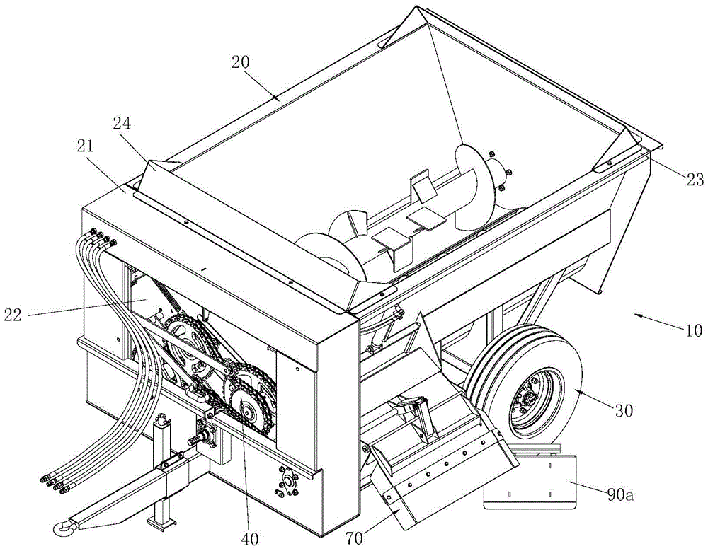
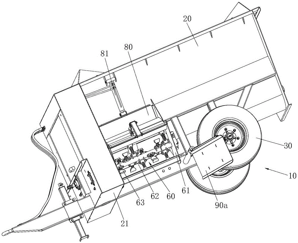
[0034] refer to Figure 2 to Figure 6 , The fertilizer applicator 10 of the present invention includes a material box 20 , a wheel 30 , a transmission mechanism 40 , a feeding auger and a fertilizer application mechanism 60 . The structure of each part is described in detail below:

[0035] At first what needs to be explained is the orientation problem. In the present invention, the front end and the rear end of the feed box are defined. Shown) under the action of power, make feed box 20 move according to the direction of traction force, therefore, the front end is the end of feed box close to traction device, and the rear end is the end of feed box away from traction device.

[0036] refer to figure 2, the top of hopper 20 has opening, and the space that is used for containing fertilizer of hopper is the bucket shape that is up big and down is small, and this bucket shape can be convenient to fertilizer and slides down automatically because its inner wall surface is the st...


PUM


Abstract

The invention discloses a fertilizer applicator. A transmission chamber with an accommodating cavity is arranged at the front end of the material box. The transmission mechanism is installed in the accommodating cavity of the transmission chamber. One end of the feeding auger is rotatably supported on the material At the rear end of the box, the other end of the feeding auger is rotatably installed at the front end of the material box and extends into the transmission chamber, and is connected with the transmission mechanism; At the mouth, the fertilizing mechanism includes a casing with openings at both ends, a rotating shaft and a fertilizing plate. The casing is fixed on the side wall of the material box. One end of the rotating shaft is rotatably supported on the casing, and the other end of the rotating shaft extends into the After entering the transmission chamber and rotatably supported on the inner wall surface of the transmission chamber, it is connected with the transmission mechanism, one end of the fertilization plate is fixed on the circumferential surface of the rotating shaft, and the other end of the fertilization plate is along the radial direction of the rotating shaft. extend. The fertilizer applicator of the invention has the advantages of high fertilization efficiency and no blockage during the fertilization process.

Description

technical field [0001] The invention relates to an automatic fertilizing device, in particular to a fertilizing machine. Background technique [0002] When fertilizing operations in rural areas, it is often necessary to quickly and evenly apply fertilizer to large areas of soil. At present, most rural areas in my country are still in the stage of artificial fertilization. This fertilization method has high labor intensity and low operation efficiency, which is difficult to meet the needs of modern agricultural production. [0003] In view of this, the patent announcement number is: the utility model patent of CN201629994U discloses a kind of small automatic fertilizer (see figure 1 ), which includes a storage device 10, a fertilizer discharge device 20 and a fertilization device 30. The storage device 10 includes a frame 11 , a storage hopper 12 , wheels 13 and an axle 14 . Wherein, the storage hopper 12 is located above the frame 11, the wheels 13 and the axle 14 are ass...

Claims


Application Information

Patent Timeline
Patent Type & Authority Patents(China)
IPC IPC(8): A01C15/16A01C19/00
Inventor 李小春孙旭亮翁志煌郭银亮
Owner 常州汉森机械股份有限公司
Why Eureka
Try Eureka