
Firm and intelligent lathe tool

An intelligent turning tool technology, applied to lathe tools, turning equipment, tool holder accessories, etc., can solve the problems that affect the service life of turning tools, cannot meet the lathe operation, reduce work efficiency, etc., and achieve good alarm Effectiveness, easy installation, and the effect of improving work efficiency

Inactive Publication Date: 2014-12-17
郑翔
View PDF1 Cites 1 Cited by
  • Summary
  • Abstract
  • Description
  • Claims
  • Application Information

AI Technical Summary

Problems solved by technology

[0002] With the development of social production, the replacement of lathes is gradually accelerating, and the birth of new lathes has also driven the continuous progress of turning tools. The turning tools on the market have a single structure and lack of functions, which can no longer meet the high-intensity and long-term demands of modern society. Lathe operation, the application number is CN96241419.0 discloses a double-headed turning tool, including two cutter heads and a cutter body, the two cutter heads are located at the diagonal position of the cutter body, and the double-head structure adopted reduces the cost of the turning tool , saving a lot of steel, but this turning tool cannot alarm when it encounters high temperature, and is easily damaged by high temperature. When the turning tool is working, the vibration phenomenon is obvious, and the turning tool is easily loosened when fixed on the tool holder, which affects the service life of the turning tool and reduces the work Efficiency, not suitable for popularization

Method used


Image

  • Firm and intelligent lathe tool
  • Firm and intelligent lathe tool

Examples


Embodiment Construction

[0015] In order to make the technical means, creative features, goals and effects achieved by the present invention easy to understand, the present invention will be further described below in conjunction with specific illustrations.

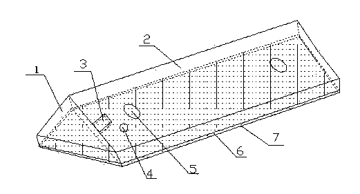
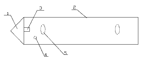
[0016] Such as figure 1 with figure 2 As shown, the firm intelligent turning tool of the present invention includes a cutter head 1 and a cutter bar 2, the cutter head 1 is connected to the cutter bar 2, and a high temperature alarm is provided on the surface of the joint between the cutter head 1 and the cutter bar 2 Light 3, a battery 4 is provided inside the knife rod, several grooves 5 are provided on the upper surface of the knife rod 2, a shock-absorbing layer 6 is provided on the lower surface of the knife rod 2, and a shock absorbing layer 6 is provided on the lower surface of the knife rod 2. There is a fine knife-tooth layer 7. When the turning tool is operating, when the temperature of the knife head exceeds the material's withstand...


PUM

PropertyMeasurementUnit
Material hardnessaaaaaaaaaa

Abstract

The invention discloses a firm and intelligent lathe tool, and relates to the field of industrial machines. The firm and intelligent lathe tool comprises a tool bit and a tool bar. The tool bit is connected with the tool bar, a high temperature warning lamp is arranged on the surface of the connecting position of the tool bit and the tool bar, and a battery is arranged inside the tool bar. A plurality of grooves are formed in the upper surface of the tool bar, a shock absorption layer is arranged on the lower surface of the tool bar, and a dense tool tooth layer is arranged on the lower surface of the shock absorption layer. When the temperature of the tool bit exceeds a material bearing temperature, the high temperature warning lamp can light up, the tip end of a blade compression device is inserted into one groove, the lathe tool can be fixed more firmly, the damping effect can be achieved in the operating process of the lathe tool through the shock absorption layer, the compression strength of a tool rest and the lathe tool can be increased through the dense tool tooth layer, when cutting resistance is large, the lathe tool cannot loose, so that cutting precision is improved, and working efficiency is improved.

Description

technical field [0001] The invention relates to the field of industrial machinery, in particular to a firm and intelligent turning tool. Background technique [0002] With the development of social production, the replacement of lathes is gradually accelerating, and the birth of new lathes has also driven the continuous progress of turning tools. The turning tools on the market have a single structure and lack of functions, which can no longer meet the high-intensity and long-term demands of modern society. Lathe operation, the application number is CN96241419.0 discloses a double-headed turning tool, including two cutter heads and a cutter body, the two cutter heads are located at the diagonal position of the cutter body, and the double-head structure adopted reduces the cost of the turning tool , saving a lot of steel, but this turning tool cannot alarm when it encounters high temperature, and is easily damaged by high temperature. When the turning tool is working, the vib...

Claims


Application Information

Patent Timeline
IPC IPC(8): B23B27/00
CPCB23B27/00B23B27/002B23B2222/28B23B2226/33
Inventor 郑翔
Owner 郑翔
Learn More