Planing machine

A planer and planing technology, which is applied in the field of woodworking machinery, can solve problems such as low work efficiency, resource waste, and increased manufacturing costs, and achieve the effects of improving automation, avoiding secondary processing, and improving production efficiency

Inactive Publication Date: 2014-12-17
ANJI DEMAI BAMBOO & WOOD MACHINERY
View PDF5 Cites 6 Cited by
  • Summary
  • Abstract
  • Description
  • Claims
  • Application Information

AI Technical Summary

Problems solved by technology

[0002] A planer is an automatic processing machine that uses a planer to plan wood. According to different requirements, woodworking planers can be divided into planers and planers, which have a single function.
During the planing process, the wood is pushed by hand for planing; during the planing process, the wood is sent to the roller to be automatically fed for planing. When both planing and pressing are required, two machines are required. It is very inconvenient to use, and increases the manufacturing cost, resulting in waste of resources
[0003] The patent number is CN200710129400, and the invention named woodworking forming planer discloses a planer. Bearings larger than the cutter shaft are installed at both ends of the cutter shaft of the prior art planer, and safety stops are installed on the planer plate edges at the two ends of the cutter shaft. The board can be used to make abrasive tools according to the needs of molding. This patent solves the problem of low efficiency of manual planing wood to a certain extent. It improves the traditional planer, but it can only plan one side of wood at a time. , low work efficiency

Method used


Image

  • Planing machine

Examples


Embodiment 1

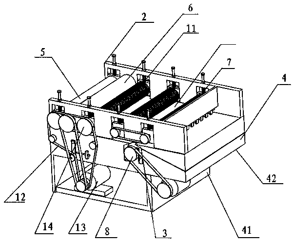
[0030] Such as figure 1 As shown, the present embodiment provides a planer, including a transmission mechanism, a frame 2, a lower planing mechanism 3 and a workbench 4, the frame 2 is arranged on the workbench 4 and props up the transmission mechanism 2, and the transmission mechanism 2 conveys and places For the wood on the workbench 4, the lower planing mechanism 3 cuts the wood delivered by the transmission mechanism 2. The transmission mechanism includes: a transmission roller 11, a transmission chain 12, a transmission motor 13 and a transmission gear 14, and the transmission motor 13 rotates to drive the transmission. Chain 12 and transmission gear 14 finally drive transmission roller 11 to rotate, and the space that timber passes is set between transmission roller 11 and workbench 4, and transmission roller 11 is arranged on the upper end of frame 2, and the quantity of transmission roller 11 is 3, conveys Anti-slip teeth are arranged on the outer surface of the roller...


PUM


Abstract

The invention discloses a planing machine, in particular a two-sided planing machine capable of planing upper and lower surfaces of a timber, and belongs to the technical field of wood-working machines. The planing machine comprises a conveying mechanism, a frame, a lower planing mechanism and a working table, wherein the frame is arranged on the working table, and supports the conveying mechanism; the conveying mechanism comprises a conveying roller, a conveying chain, a conveying motor and a conveying gear; the conveying motor rotates to drive the conveying chain and the conveying gear and to finally drive the conveying roller to rotate; a timber passing space is formed between the conveying roller and the working table; the lower planing mechanism is arranged on the working table; the working table comprises a fixed table and a movable table; the movable table vertically moves, and fits the conveying roller to clamp the timber; and an upper planing mechanism is additionally arranged on the frame. The planing machine can synchronously plane the upper and lower end surfaces of the timber to prevent secondary processing, so that the production efficiency is improved, and the energy consumption is reduced.

Description

technical field [0001] The invention discloses a planer, in particular to a double-sided planer capable of planing wood on both sides up and down, and belongs to the technical field of woodworking machinery. Background technique [0002] A planer is an automatic processing machine that uses a planer to plan wood. According to different requirements, woodworking planers can be divided into planers and planers, which have a single function. During the planing process, the wood is pushed by hand for planing; during the planing process, the wood is sent to the roller to be automatically fed for planing. When both planing and pressing are required, two machines are needed. It is very inconvenient to use, and increases the manufacturing cost, resulting in waste of resources. [0003] The patent number is CN200710129400, and the invention named woodworking forming planer discloses a planer. Bearings larger than the cutter shaft are installed at both ends of the cutter shaft of the...

Claims


Application Information

Patent Timeline
Patent Type & Authority Applications(China)
IPC IPC(8): B27C1/08B27C1/12
Inventor 马明海
Owner ANJI DEMAI BAMBOO & WOOD MACHINERY
Why Eureka
Try Eureka