Table-type cutting machine and cutting work table thereof

A desktop cutting machine and workbench technology, applied in work accessories, manufacturing tools, metal sawing equipment, etc., can solve problems such as potential safety hazards and achieve the effect of preventing miscuts

Active Publication Date: 2014-12-17
NANJING CHERVON IND
View PDF6 Cites 5 Cited by
  • Summary
  • Abstract
  • Description
  • Claims
  • Application Information

AI Technical Summary

Problems solved by technology

[0002] As a cutting equipment for tiles and other stone materials, desktop cutting machines often use circular saw blades as cutting tools. During processing, the fixed saw blades are often used to drive the fixed stones to be cut by moving the work surface. Cutting, but we know that the work surface can only slide in one direction, which is often the horizontal direction. Due to the contour of the circular saw blade, if the flat stone is only placed flat on the work surface for cutting, due to the flat stone thickness, the final incision is an arc (refer to figure 1 shown), but in fact what we need is a flat cut that is nearly straight. At this time, it is often necessary to lift the stone manually to make it tilted to a flat cut (refer to figure 2 shown), but this depends on the operator's personal skills and proficiency, and there is a great potential safety hazard

Method used


Image

  • Table-type cutting machine and cutting work table thereof
  • Table-type cutting machine and cutting work table thereof
  • Table-type cutting machine and cutting work table thereof

Examples


Embodiment Construction

[0032] The present invention will be specifically introduced below in conjunction with the accompanying drawings and specific embodiments.

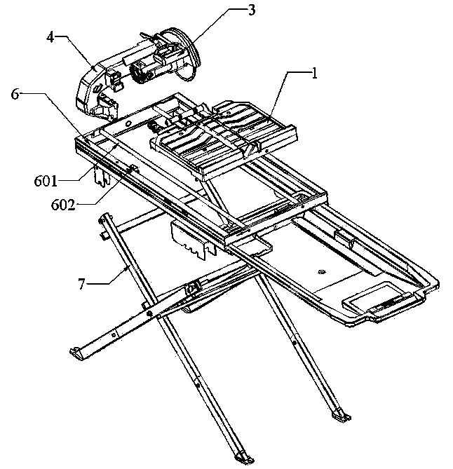
[0033] refer to Figure 3 to Figure 5 As shown, the desktop cutting machine of the present invention mainly includes: a cutting head assembly 3, a cantilever assembly 4, a machine base, a cutting workbench, a workbench bracket 5, and an accommodation cavity; wherein, the machine base includes: a frame 6, a folding bracket 7 , the cantilever rotating shaft 203, the driving end 204, and the installation notch 105.

[0034] Wherein, the cutting head assembly 3 and the cantilever assembly 4 form an integral body, the cantilever assembly 4 is used to support the cutting head assembly 3, and the whole they constitute is fixed on the top of the frame 6, and the frame 6 is provided with a slide rail 601, and the cutting table and The workbench bracket 5 constitutes a whole and forms a sliding connection with the frame 6 through the slide rail 60...


PUM


Abstract

A cutting worktable includes a worktable body have a distal side located away from a cutting tool and a proximal side located adjacent to the cutting tool. The cutting worktable further includes a support frame assembly disposed at the proximal side of the worktable body and used to lift an object to be cut so that the object to be cut is placed on a top surface of the worktable body in an inclined posture. The support frame assembly includes a support roller for contacting the object to be cut and the worktable body is provided with a limiting structure for abutting against the object to be cut and limiting its position. The object to be cut can thus be inclined via the support frame assembly and fixed by the limiting structure. The limiting structure can be in the form of a plurality of placement grooves to achieve placement of the object to be cut at different angles relative to the cutting tool and worktable.

Description

technical field [0001] The invention relates to a desktop cutting machine and its cutting workbench, in particular to a desktop cutting machine and its cutting workbench for cutting tiles and other stone materials. Background technique [0002] As a cutting equipment for tiles and other stone materials, desktop cutting machines often use circular saw blades as cutting tools. During processing, the fixed saw blades are often used to drive the fixed stones to be cut by moving the work surface. Cutting, but we know that the work surface can only slide in one direction, which is often the horizontal direction. Due to the contour of the circular saw blade, if the flat stone is only placed flat on the work surface for cutting, due to the flat stone thickness, the final incision is an arc (refer to figure 1 shown), but in fact what we need is a flat cut that is nearly straight. At this time, it is often necessary to lift the stone manually to make it tilted to a flat cut (refer to...

Claims


Application Information

Patent Timeline
Patent Type & Authority Applications(China)
IPC IPC(8): B28D1/04B28D7/04
CPCB28D1/047B23D45/02B23D47/045B28D7/04B28D7/043
Inventor 陈智丰
Owner NANJING CHERVON IND
Why Eureka
Try Eureka