Hanging device for controlling release through hydraulic pressure difference and release controlling method thereof

A technology for controlling release and suspension devices, applied in the field of drilling, which can solve problems such as increased chance of rework, polluted wellhead, unrecoverable steel balls, etc., and achieves the effect of improving the success rate

Active Publication Date: 2014-12-17
PETROCHINA CO LTD
View PDF5 Cites 0 Cited by
  • Summary
  • Abstract
  • Description
  • Claims
  • Application Information

AI Technical Summary

Problems solved by technology

[0002] At present, many oil wells use tools such as sliding sleeves and suspensions in the downhole tools to achieve a certain purpose according to their technology. After going into the well, whether it is a sliding sleeve or a hand-dropping tool, it is basically solved by throwing a ball to suppress the pressure. The current method There are great limitations. Some processes will have multiple multi-stage pressure suppression, and there is no salvage bar, and the steel balls cannot be recovered, resulting in complex downhole conditions; And the difficulty of operation is increased, the wellhead is seriously polluted, and the working environment of the operators is harsh
Secondly, the chance of rework increases due to the inability to drop hands

Method used


Image

  • Hanging device for controlling release through hydraulic pressure difference and release controlling method thereof

Examples


Embodiment 1

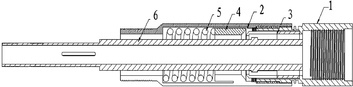
[0018] Such as figure 1 As shown, a suspension device using hydraulic pressure difference to control the release is composed of an upper joint 1, a device body 2, slips 3, a differential pressure sliding sleeve 4, a spring 5, and a bearing joint 6. The upper joint 1 and the device body 2 It is connected through the oil pipe buckle, the oil pipe buckle is the oil casing joint screw, the slip 3 is nested in the upper joint 1, the differential pressure sliding sleeve 4 and the spring 5 are nested in the device body 2, and the outer diameter of the bearing joint 6 is connected with a pressure The differential sliding sleeve 4, the spring 5, and the bearing joint 6 are positioned and suspended at the slip 3, and the designed suspension weight is 30KN;

[0019] The outer diameters of the upper joint 1 and the device body 2 are both φ95mm or greater than φ95mm;

[0020] The upper joint 1 is connected to the device body 2 through a φ73mm tubing buckle, or a tubing buckle larger than ...

Embodiment 2

[0024] A controlled release method using hydraulic pressure difference, comprising the following steps:

[0025] After the running tool is connected to the suspension device controlled by the hydraulic pressure difference, the suspension device released by the hydraulic pressure difference is lowered into the predetermined position in the well, and the workover fluid is pumped from the tubing. When the pressure difference reaches 3-4Mpa, the pressure The differential sliding sleeve 4 goes down, and when the driving force of the differential pressure sliding sleeve 4 exceeds the starting force of the spring 5, the differential pressure sliding sleeve 4 moves down to break away from the supporting surface of the supporting slips, and the slips 3 are opened at this time, and the bearing joint 6 and the corresponding The connecting tools are released and dropped together to achieve the intended purpose, and the differential pressure sliding sleeve 4 returns automatically under the ...

Embodiment 3

[0029] A suspension device controlled by hydraulic pressure difference, which is composed of an upper joint 1, a device body 2, slips 3, a differential pressure sliding sleeve 4, a spring 5, and a bearing joint 6. The outer diameter of the upper joint 1 and the device body 2 is Both are φ95mm, the upper joint 1 and the device body 2 are connected by a φ73mm oil pipe buckle through the connecting thread, the bearing joint 6 has an outer diameter of φ46mm, an inner diameter of φ28mm, slips 3 are nested in the upper joint 1, differential pressure sliding sleeve 4, spring 5 Nested in the device body 2, the diameter of the device body 2 is φ52mm, the bearing joint 6 is positioned and suspended at the slip 3, and the design suspension weight is 30KN.

[0030] The slips 3 are connected in rotation relative to the upper joint 1 .

[0031] The device body 2 is nested with a differential pressure sliding sleeve 4 and a spring 5, and one side of the differential pressure sliding sleeve 4...


PUM


Abstract

The invention discloses a hanging device for controlling release through hydraulic pressure difference and a release controlling method thereof, and belongs to the drilling technical field. After a well descending tool is connected with the hanging device for controlling release through the hydraulic pressure difference, the hanging device for controlling release through the hydraulic pressure difference is tripped into a preset position inside a well, workover fluid is pumped therein from the inside of an oil pipe, and when the pressure difference value reaches 3-4 MPa, a pressure difference sliding sleeve descends; when the pressure difference sliding sleeve driving force exceeds spring starting force, the pressure difference sliding sleeve moves downwards to the position which is disengaged from a supporting face used for supporting a slip, at the moment, the slip is opened, a bearing connector and the well descending tool connected with the bearing connector are released to fall together, so that an expected purpose is achieved, the pressure difference sliding sleeve returns automatically under the action of a spring, and the pressure difference sliding sleeve can be cleaned and maintained to be used continuously after being pulled out. By means of the hanging device for controlling release through the hydraulic pressure difference and the release controlling method, the phenomenon that ball throwing is conducted for a long time, no fishing devices exist, and thus the downhole condition is complex can be avoided, it is guaranteed that the downhole operating environment cannot be polluted, and cleanliness and sanitation are achieved; after the method is matched with a pipe inner sand washing technology, the problem that an inner wash pipe can be stuck when returning to the oil pipe in the sand washing process is solved, and therefore the continuous sand washing purpose can be achieved.

Description

technical field [0001] The invention relates to a suspension device and a method for controlling release by using hydraulic pressure difference, belonging to the technical field of drilling. Background technique [0002] At present, many oil wells use tools such as sliding sleeves and suspensions in the downhole tools to achieve a certain purpose according to their technology. After going into the well, whether it is a sliding sleeve or a hand-dropping tool, it is basically solved by throwing a ball to suppress the pressure. The current method There are great limitations. Some processes will have multiple multi-stage pressure suppression, and there is no salvage bar, and the steel balls cannot be recovered, resulting in complex downhole conditions; And the difficulty of operation is increased, the wellhead is seriously polluted, and the working environment of the operators is harsh. Secondly, due to the inability to drop hands, the probability of rework increases. Content...

Claims


Application Information

Patent Timeline
Patent Type & Authority Applications(China)
IPC IPC(8): E21B21/00
Inventor 师成灿
Owner PETROCHINA CO LTD
Why Eureka
Try Eureka