
Hydraulic balance temperature adjusting method

A technology of hydraulic balance and temperature adjustment, applied in the field of HVAC, can solve the problems of long debugging time, complicated steps, time-consuming and labor-intensive, etc., and achieve the effect of low power consumption and fast and accurate adjustment.

Inactive Publication Date: 2014-12-17
卓旦春
View PDF8 Cites 17 Cited by
  • Summary
  • Abstract
  • Description
  • Claims
  • Application Information

AI Technical Summary

Problems solved by technology

[0003] Although the current methods commonly used to solve the hydraulic balance can achieve certain results, the debugging time is too long and the steps are complicated and time-consuming.

Method used


Image

  • Hydraulic balance temperature adjusting method

Examples


Embodiment Construction

[0030] The following are specific embodiments of the present invention and in conjunction with the accompanying drawings, the technical solutions of the present invention are further described, but the present invention is not limited to these embodiments.

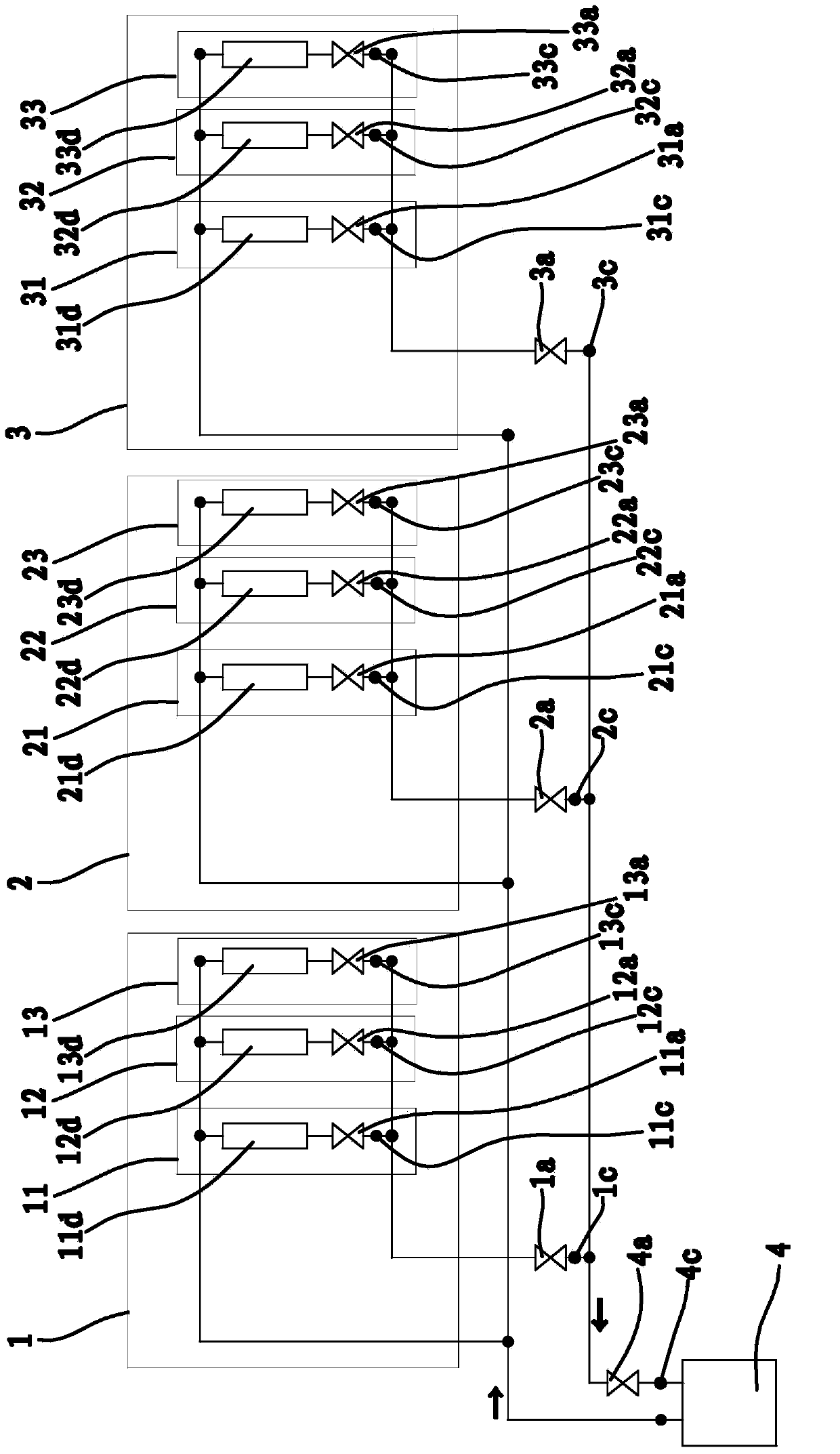
[0031] Such as figure 1 As shown, the heating source 4 supplies water to the pipeline system, and the valve 13 4a controls the flow of the total loop. Test point 13 4c is used to measure the total return water temperature of heating source 4 .

[0032] The general ring includes main ring one 1 , main ring two 2 , and main ring three 3 .

[0033] Valve ten 1a controls the flow of main loop one 1. Test point 1c is used to measure the return water temperature of main loop 1.

[0034] Valve eleven 2a controls the flow of main loop two 2 . Test point 11 2c is used to measure the return water temperature of main loop 2 2 .

[0035] Valve twelve 3a controls the flow of main loop three 3 . Test point 12 3c is used to measure...


PUM


Abstract

The invention provides a hydraulic balance temperature adjusting method, and belongs to the technical field of heating, which solves the problem of overlong adjusting time of the existing hydraulic balance adjusting method. The adjusting method comprises the following steps of a, opening all valves, and filling water; b, determining the most adverse loop, wherein the loop with lowest water return temperature is determined as the most adverse loop, and adjusting the most adverse loop; c, adjusting the water return temperature of each main loop and each branch loop, considering compensate temperature, and enabling the water return temperature of each loop to be equal to the total water return temperature; finally, spot-checking a plurality of branch loops, and guaranteeing the accuracy of the adjusted structure. The adjusting method has the advantages that the electric consumption amount of a water pump is less, and the adjusting is rapid and accurate.

Description

technical field [0001] The invention belongs to the technical field of heating and ventilation, and relates to a temperature adjustment method, in particular to a hydraulic balance temperature adjustment method. Background technique [0002] In HVAC systems, hydraulic imbalances often occur. The hydraulic imbalance is essentially that the flow of some users in the system is too large, and the unfavorable loop users cannot obtain the required flow. The specific performance is that the room of some users cannot reach the design temperature, while the room temperature of some users is too high, and even the windows are opened for ventilation. In order to solve this contradiction, some people propose to increase the flow rate of pipelines in the system and meet the needs of unfavorable loops by increasing energy consumption, thinking that this will cover up the existence of hydraulic imbalance. This method, on the surface, may slightly alleviate the unfavorable room temperatur...

Claims


Application Information

Patent Timeline
Patent Type & Authority Applications(China)
IPC IPC(8): F24D3/02F24D19/10
Inventor 卓旦春
Owner 卓旦春
Learn More