
Fan motor stator and manufacturing method

A technology of fan motor and manufacturing method, which is applied in the field of fan motor stator manufacturing, can solve the problems of high production cost, many enameled wires, and great difficulty, and achieve the effects of simple manufacturing process, reduced metal consumables, and reduced production cost

Active Publication Date: 2015-06-17
佛山市吉星家电有限公司
View PDF4 Cites 0 Cited by
  • Summary
  • Abstract
  • Description
  • Claims
  • Application Information

AI Technical Summary

Problems solved by technology

The above-mentioned stator structure and manufacturing method have the following disadvantages: ①Due to the use of manual drop-off, the upper and lower parts of the main and auxiliary windings must be higher than the thickness of the stator core by a certain distance, for example, 1-2cm; , The weight of the enameled wire in the higher part of the auxiliary winding accounts for about 25-30% of the total weight of the enameled wire of the winding
Therefore, the manual drop-off consumes more enameled wires and the production cost is high
②Because the stator has 16 wire slots, the number of windings is large and difficult, and it is easy to scratch or break the enameled wire. The number of insulating slot papers to be placed is large and the positions are difficult to be even, resulting in low production efficiency and unstable quality.
③There are many windings and more taps. It is necessary to use a multimeter to find the matching wire ends. It is very complicated to fix and shape the paper and wiring ends
In short, the manufacturing process of the stator structure box of the fan motor mentioned above is complicated, requires a lot of labor, consumes a lot of copper materials, the product quality is unstable, and the production efficiency is low.

Method used


Image

  • Fan motor stator and manufacturing method
  • Fan motor stator and manufacturing method
  • Fan motor stator and manufacturing method

Examples


Embodiment Construction

[0032] The present invention is described in further detail by the following examples.

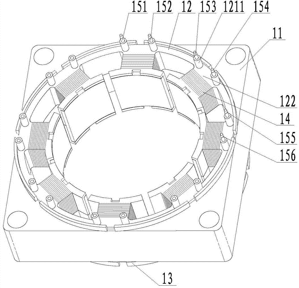
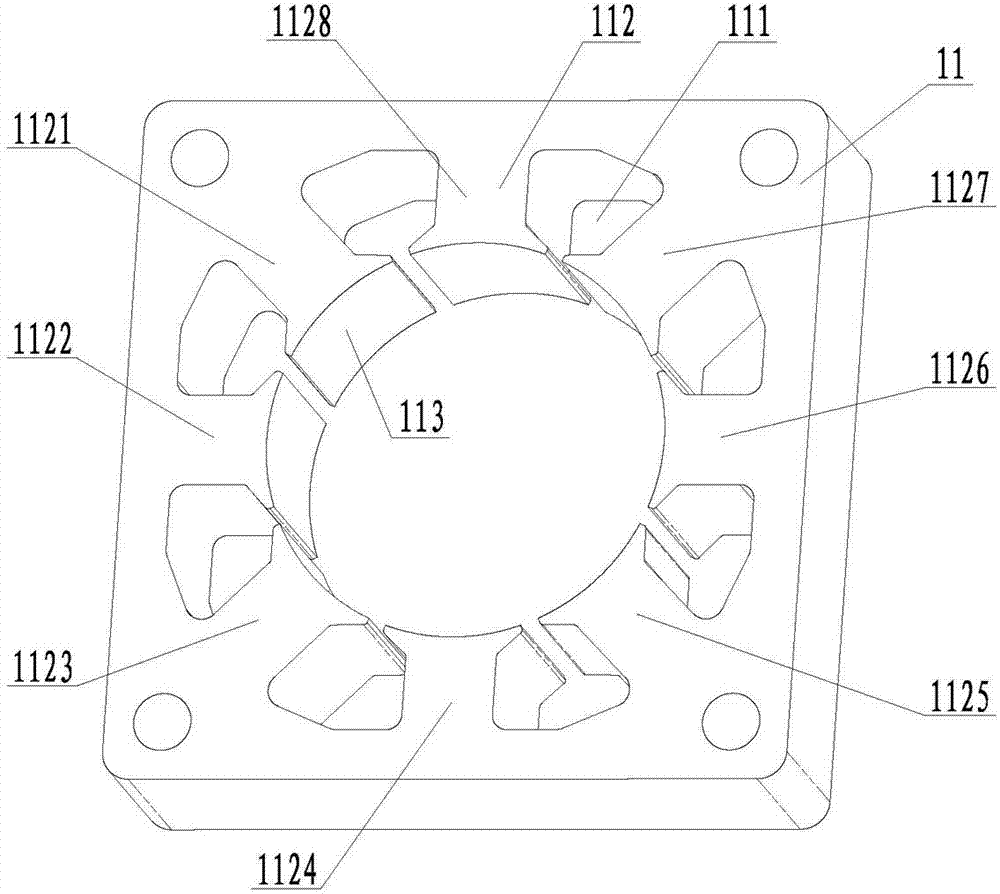
[0033] see Figure 2-Figure 12 As shown, a fan motor stator is mainly composed of a stator core 11, an upper frame 12, a lower frame 13, a main winding 141 and three auxiliary windings. The main and auxiliary windings 14 include the main winding 141 and three auxiliary windings. The main and auxiliary windings 14 are connected in parallel with capacitors C. The stator core 11 is evenly arranged along the ring circle with 8 iron yokes 112, 8 pole shoes 113 and 8 wire slots. 111, each slot 111 is fan-shaped and has a relatively large cross-sectional area, each iron yoke 112 is square, and the intersecting angle between the center lines of two adjacent iron yokes 112 is 45°. It is also provided with an upper frame 12 and a lower frame 13 that are matched with each other. The lower part of the annular upper plate 125 of the upper frame 12 is evenly provided with 8 fan-shaped upper hollow groo...


PUM


Abstract

The invention provides a fan motor stator and a manufacturing method. The stator is mainly composed of a stator core, an upper framework, a lower framework, a main winding and three auxiliary windings; eight sector wiring ducts, eight square iron yokes 112 and eight pole shoes are evenly arranged on the stator; the upper and lower frameworks matched with the stator core in shape are connected in an abutting embedment manner to cover the stator core; the main winding is connected in series and wound around the odd-number iron yokes of the stator core and the first, second and third auxiliary windings are orderly connected in series and wound around the even-number iron yokes of the stator core by use of an automatic winding machine and the frameworks; tab leads are wound around and welded on the corresponding binding posts of the upper framework, respectively. The fan motor stator has the advantages that wires are directly around the iron yoke frameworks by use of the automatic winding machine and the tab leads are welded, and therefore, the manufacturing process of the stator is simple, the quality of the product is good, more than 25% of varnished wires and metal materials can be saved, and as a result, the production cost is greatly reduced and the production efficiency is high.

Description

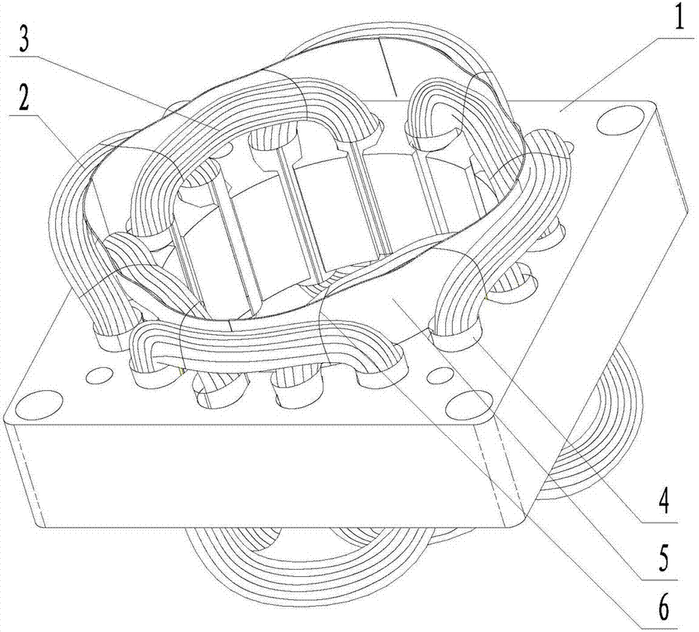
technical field [0001] The invention relates to the technical field of AC squirrel-cage motors, in particular to a method for manufacturing a stator of a fan motor. Background technique [0002] The fan motor generally adopts an AC squirrel-cage motor. There are 16 slots in the stator 1 of an existing fan motor, the slots are elliptical, and the cross-sectional area is small, see figure 1 shown. The stator structure and manufacturing process of this fan motor are as follows: First, the main winding coil 2 and the auxiliary winding coil 3 are wound, and then the insulating slot paper 4 is inserted into the stator slot, and the wound main and auxiliary coils 2 and 3 are pressed Manually fall into the wire slot in order, separate the main winding 2 and the auxiliary winding 3 with insulating paper (green shell paper) 5, use a multimeter to measure the wire end of the gear position, connect the lead wire of the corresponding gear position, weld and put it on For the insulatin...

Claims


Application Information

Patent Timeline
Patent Type & Authority Patents(China)
IPC IPC(8): H02K1/16H02K3/28H02K15/02H02K15/085
Inventor 黄宝钗吴树填曾显祥张兆芝
Owner 佛山市吉星家电有限公司
Learn More