Method for electron tomography

An electronic tomography and imaging technology, applied in computer tomography scanners, material analysis using wave/particle radiation, circuits, etc., can solve problems such as time-consuming tilt series

Active Publication Date: 2014-12-24
FEI CO
View PDF5 Cites 5 Cited by
  • Summary
  • Abstract
  • Description
  • Claims
  • Application Information

AI Technical Summary

Problems solved by technology

As a result of this situation, the acquisition of the tilt series is a time-consuming process

Method used


Image

  • Method for electron tomography
  • Method for electron tomography
  • Method for electron tomography

Examples


Embodiment Construction

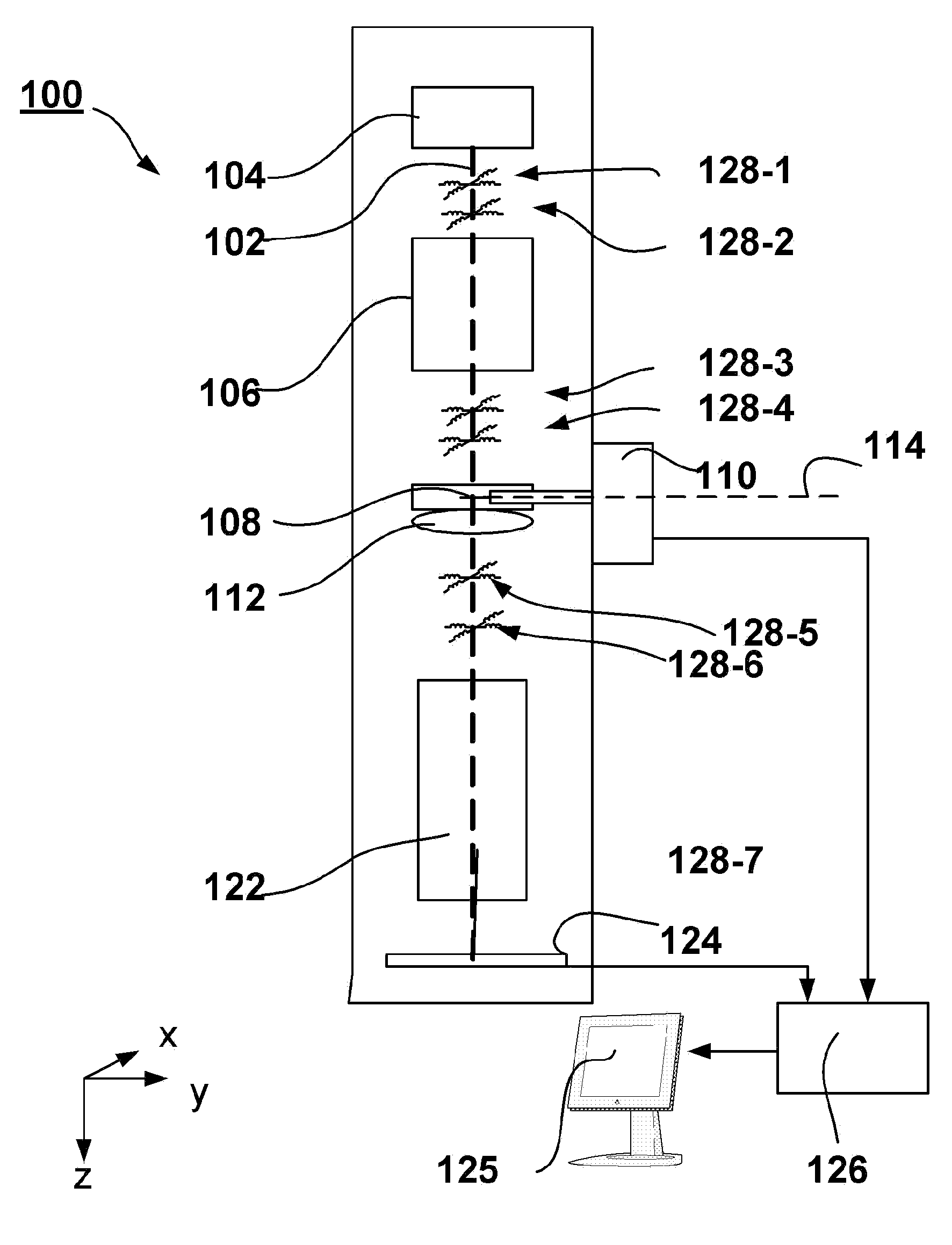
[0041] figure 1 A TEM 100 is shown schematically. Particle source 104 generates a beam of electrons along optical axis 102 . Electrons have a selectable energy typically between 80-300 keV, although higher energies (eg 400 keV-1 MeV) or lower energies (eg 50 keV) can be used. The electron beam is steered by a condenser lens system 106 to form a parallel beam that impinges on a sample 108 , which is positioned using a sample holder 110 . The sample holder can position the sample relative to the optical axis and can offset the sample in a plane perpendicular to the optical axis and tilt the sample relative to a tilt axis 114 perpendicular to the optical axis. Objective lens 112 forms a magnified image of the sample. Projection system 122 forms a magnified image of the sample on pixelated detector 124, thereby revealing sample details, eg, 0.1 nm. The detector can take the form of a CCD or CMOS camera, for example.

[0042] To align the on-axis optics, the TEM includes a lar...


PUM


Abstract

The invention relates to an improved method of electron tomography. Electron tomography is a time consuming process, as a large number of images, typically between 50-100 images, must be acquired to form one tomogram. The invention teaches a method to shorten the time needed to acquire this amount images much more quickly by tilting the sample continuously, instead of step-by-step. Hereby the time needed to reduce vibrations between steps is eliminated.

Description

technical field [0001] The invention relates to a method of performing electron tomography on a sample mounted on a sample holder in an electron microscope comprising an electron source for generating an energetic electron beam along an optical axis, and Optics for focusing and deflecting a beam to irradiate a sample with an electron beam, the sample holder enables orientation and tilting of the sample with respect to the electron beam, the method comprising acquiring a tilt series of images by irradiating the sample with the electron beam (tilt series), each image is acquired at an associated unique tilt angle, and the images are recorded on the camera at read-out speed. [0002] See, among other things, FEI's "Technical note: Functional description of Tecnai TM Tomography Software", December 31, 2003 version is aware of such a method. Background technique [0003] In an electron microscope, such as a transmission electron microscope (TEM), an electron source produces an...

Claims


Application Information

Patent Timeline
Patent Type & Authority Applications(China)
IPC IPC(8): A61B6/03
CPCG01N23/046H01J37/20H01J37/22H01J37/28H01J2237/20207H01J2237/20228H01J2237/20235H01J2237/20264H01J2237/20285H01J2237/2802
Inventor U. 鲁伊肯R. 肖恩马克斯J. A. M. 安托纽斯
Owner FEI CO
Why Eureka
Try Eureka