A kind of multifunctional manual dilator
What is Al technical title?
Al technical title is built by PatSnap Al team. It summarizes the technical point description of the patent document.
A dilator and multi-functional technology, applied in the field of dilator equipment and multi-functional manual dilators, to achieve the effect of meeting the needs, simple operation and expanding the scope of application
Active Publication Date: 2016-08-24
HAIYAN AIHUA MACHINERY CO LTD
View PDF14 Cites 0 Cited by
Summary
Abstract
Description
Claims
Application Information
AI Technical Summary
This helps you quickly interpret patents by identifying the three key elements:
Problems solved by technology
Method used
Benefits of technology
Problems solved by technology
[0003] The purpose of the present invention is to solve the problems in the prior art, and propose a multifunctional manual expander, which can expand the compressed object through the up and down movement of the rocker, with simple structure, light weight, convenient transportation and high work efficiency , large load-bearing mass, easy maintenance, can greatly expand the function of the manual expander, can meet more functional requirements, adapt to more complex environments, can make multiple expanders work better together, and meet greater forces Reliable cooperation, safer, can make the dilator rotate on the base as needed, and can use rope or chain to realize the pulling function, simple structure, convenient operation, which greatly expands the use function of the dilator
Method used
Image
Click on the blue label to locate the original text in one second.
Reading with bidirectional positioning of images and text.
Examples
Embodiment Construction
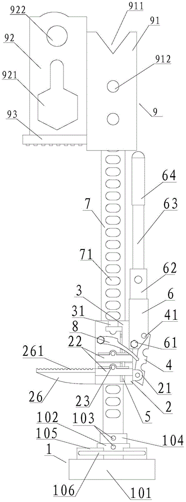
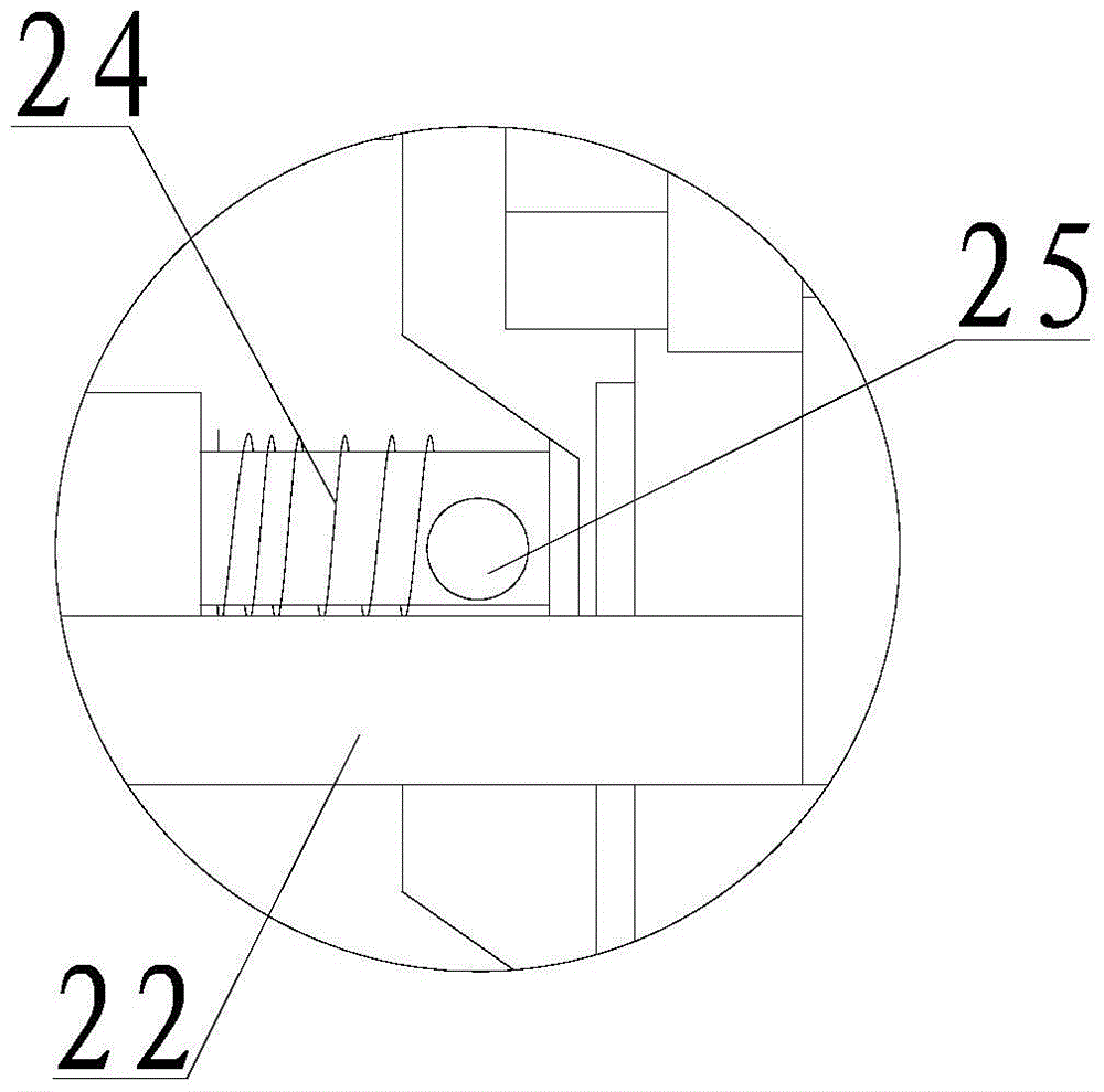
[0029] refer to figure 1 , figure 2 , image 3 , Figure 4 , Figure 5 , Image 6 , Figure 7 , Figure 8 , Figure 9 , Figure 10 , Figure 11 ,and Figure 12, a multi-functional manual expander of the present invention, including load-bearing base 2, crawling base 3, connecting rod 4, ascending pull plate 5, ascending rocker seat 6, climbing plate 7, auxiliary sleeve 9 and locking plate 8, the The crawling seat 3 and the load-bearing seat 2 are respectively sleeved on the climbing plate 7, and the climbing plate 7 is provided with a number of climbing holes 71, and the two sides of the load-bearing seat 2 are respectively provided with a load-bearing platform 26 and a hinged seat 21, and the hinged seat 21 is passed through a pin 41 is hingedly equipped with a connecting rod 4, the load-bearing seat 2 and the crawling seat 3 are respectively provided with a horizontal pin seat 22, the crawling seat 3 is provided with a guide seat 31, and the guide seat 31 is equip...
PUM
Abstract
The invention discloses a multifunctional manual expander, which comprises a bearing seat, a crawling seat, a connecting rod, a step-up pull plate, a step-up rocker seat, a climbing plate, an auxiliary sleeve and a locking piece, and the crawling seat and the load-bearing seat are respectively covered with On the climbing plate, a number of climbing holes are arranged on the climbing plate, bearing platforms and hinged seats are respectively arranged on both sides of the bearing seat, connecting rods are hingedly installed on the hinged seats, and auxiliary sleeves are installed on the climbing holes to assist The sleeve includes a sliding sleeve on which a pressing table is fixed, and a matching plate is arranged on the upper part of the pressing table, a number of sliding sleeve pin holes are arranged on the sliding sleeve, a fixing groove is arranged on the sliding sleeve, and a fitting plate is arranged on the matching plate. Cooperate with the round hole and the polygonal hole, the bottom plate is provided with a fixed sleeve, a number of reinforcing plates are provided around the fixed sleeve, a support rod is provided between the reinforcing plates, and a rotating sleeve is provided in the fixed sleeve. cylinder. The invention has the advantages of simple structure, light weight, convenient transportation and carrying, high working efficiency, large load-bearing quality and easy maintenance.
Description
【Technical field】 [0001] The invention relates to the technical field of dilator equipment, in particular to the technical field of a multifunctional manual dilator. 【Background technique】 [0002] The expander is a rescue tool, mainly used in the field of firefighting. It can spread heavy objects and rescue people trapped below. At present, full hydraulic pressure is used as the power source for firefighting. This kind of equipment requires high precision parts and low failure rate. High, inconvenient maintenance, complex structure, heavy weight, inconvenient transportation and slow speed, can not meet the needs of fire rescue. At present, some companies have developed screw-type expanders, although the quality It is lighter, but the load-bearing capacity is small and the speed is slow, which still cannot meet the needs. The market needs an expansion device with light weight, large load-bearing capacity, simple structure, and convenient maintenance. At the same time, the e...
Claims
Application Information
Patent Timeline
Application Date:The date an application was filed.
Publication Date:The date a patent or application was officially published.
First Publication Date:The earliest publication date of a patent with the same application number.
Issue Date:Publication date of the patent grant document.
PCT Entry Date:The Entry date of PCT National Phase.
Estimated Expiry Date:The statutory expiry date of a patent right according to the Patent Law, and it is the longest term of protection that the patent right can achieve without the termination of the patent right due to other reasons(Term extension factor has been taken into account ).
Invalid Date:Actual expiry date is based on effective date or publication date of legal transaction data of invalid patent.