Back-blowing flue gas filtering system and operating method thereof

A filtration system and working method technology, applied in separation methods, dispersed particle filtration, chemical instruments and methods, etc., can solve problems such as backflush flue gas containing dust, reduce the difficulty of cleaning dust, and increase the gap between filter bags and cages, etc. To achieve the effect of improving technical advantages, improving market competitiveness, and avoiding dust accumulation in filter bags

Inactive Publication Date: 2014-12-24
李毅 +1
View PDF0 Cites 3 Cited by
  • Summary
  • Abstract
  • Description
  • Claims
  • Application Information

AI Technical Summary

Problems solved by technology

[0006] Aiming at the deficiencies of the above-mentioned existing blowback bag-type dust removal technology, the technical problem to be solved by the present invention is how to provide a blowback flue gas filtration system in the blowback pipeline, so that when the filter bag is broken, the dust-laden blowback flue gas can be Realize secondary filtration and solve the above-mentioned backflushing dust accumulation problem inside the filter bag
Later, this kind of project was more modified, and the gap between the filter bag and cage was adjusted to reduce the difficulty of cleaning. After the transformation, the original booster fan does not need to be started for a long time. Under this background, if a The back blowing flue gas filter device uses the original back blowing booster fan to offset the resistance caused by the addition of the back blowing flue gas filter device, which can solve the filtration of dust in the back blowing flue gas under the premise of meeting the pressure of back blowing dust removal question

Method used


Image

  • Back-blowing flue gas filtering system and operating method thereof

Examples


Embodiment Construction

[0020] The specific implementation plan is as follows:

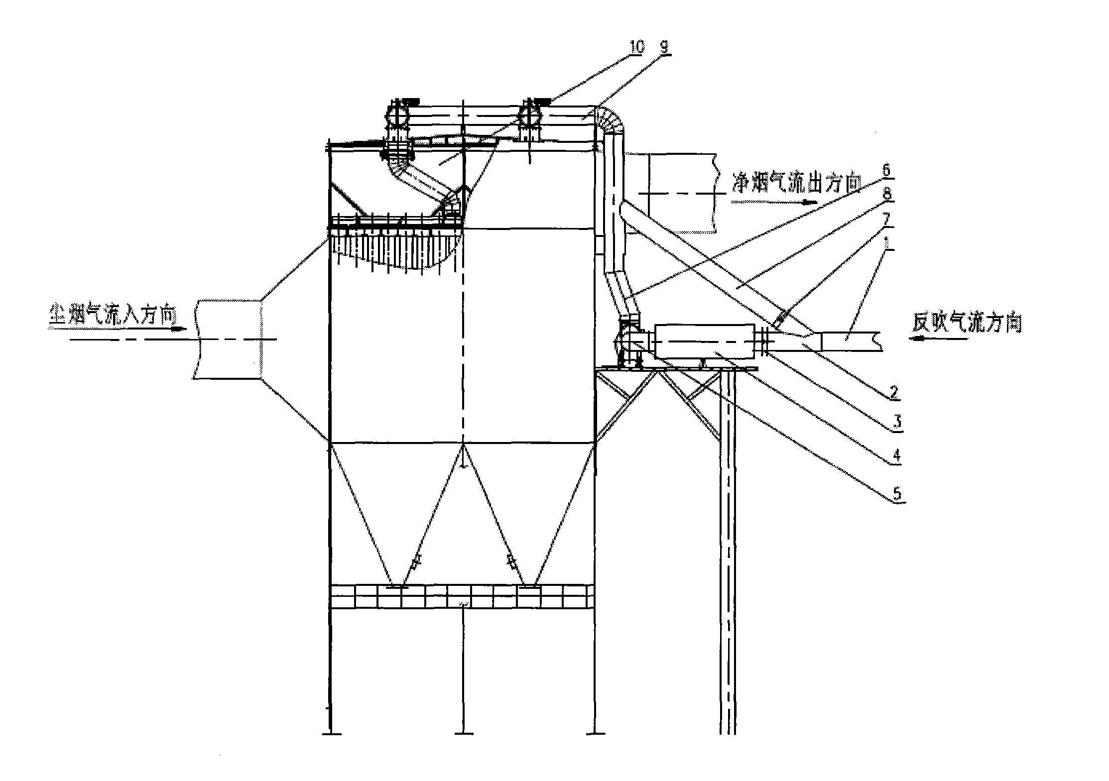
[0021] A backflush flue gas filtering system, comprising one or more backflush pipelines (1) drawn from a backflush gas source, each backflush pipeline is provided with a three-way (2), and a valve one (3), Valve two (7), valve one (3) are connected to back blowing section one (6), and back blowing section one is connected in series with back blowing flue gas filter device (4), back blowing booster fan (5), back blowing section One end is connected to the dust removal system (9) of the blowback bag filter; the second valve (7) is connected to the second blowback section (8), and the second blowback section (8) is directly connected to the dust removal system of the blowback bag filter (9) connected, back blowing section one (6) and back blowing section two (8) are in parallel relationship, this back blowing flue gas filtration system is used in the back blowing bag filter When the filter bag is damaged and the dust cont...


PUM


Abstract

The invention discloses a back-blowing flue gas filtering system and an operating method thereof. The back-blowing flue gas filtering system comprises one or more back-blowing pipes (1) educed from a back-blowing gas source, each back-blowing pipe (1) is provided with a tee joint (2), a valve 1 (3) and a valve 2 (7) are arranged behind the tee joint (2), a back-blowing section 1 (6) is connected behind the valve 1 (3), the back-blowing section 1 is connected in series with a back-blowing flue gas filtering device (4) and a back-blowing booster fan (5), and the tail end of the back-blowing section 1 is connected with a back-blowing bag type dust remover dust cleaning system (9); and a back-blowing section 2 (8) is connected behind the valve 2 (7), the back-blowing section 2 (8) is directly connected with the back-blowing bag type dust remover dust cleaning system (9), and the back-blowing section 1 (6) is connected in parallel with the back-blowing section 2 (8). The back-blowing flue gas filtering system is used in a back-blowing bag type dust remover, and when the dust content of back-blowing flue gas is high because a filter bag of the back-blowing bag type dust remover is damaged, the filtering system is started for carrying out secondary filtering, so that the problem that dust is accumulated in the filter bag due to the back-blowing of dust-containing flue gas is solved.

Description

technical field [0001] The invention relates to a back-blowing flue gas filtering system and a working method thereof, which are used in a back-blowing bag type dust collector. Background technique [0002] At present, bag filter is widely used in industry to purify dusty gas produced in metallurgy, mining, chemical industry, cement, power generation, grain processing and other industries. The working principle of the bag filter is to introduce the dust-laden gas into the filter bag and let it pass through the filter bag in the filter bag. The dust particles are intercepted and left on the surface of the filter bag to form a dust layer. The clean air flows out of the dust collector through the filter bag smoothly. After running for a period of time, the dust layer accumulated on the dust-facing surface of the bag filter bag becomes thicker and thicker, which increases the resistance loss of the dust collector. Therefore, after the bag filter has been running for a period o...

Claims


Application Information

Patent Timeline
Patent Type & Authority Applications(China)
IPC IPC(8): B01D46/02B01D46/04
Inventor 李毅高境
Owner 李毅
Why Eureka
Try Eureka