Apparatus for printing on a curved surface of an object through an ink jet print head

A technology of inkjet printing and printing head, which is applied in printing, transfer materials, power transmission devices, etc., can solve problems such as deviation and achieve the effect of reducing reliability

Inactive Publication Date: 2014-12-24
HEIDELBERGER DRUCKMASCHINEN AG
View PDF13 Cites 10 Cited by
  • Summary
  • Abstract
  • Description
  • Claims
  • Application Information

AI Technical Summary

Problems solved by technology

[0011] The mentioned compensation methods based on printing data or nozzle control may also have the disadvantage that, for example, these compensation methods are computationally intensive and are not sufficient in the case where the Deviations from the nominal values ​​(e.g. position, orientation, velocity, acceleration) of the print head during movement

Method used


Image

  • Apparatus for printing on a curved surface of an object through an ink jet print head
  • Apparatus for printing on a curved surface of an object through an ink jet print head
  • Apparatus for printing on a curved surface of an object through an ink jet print head

Examples


Embodiment Construction

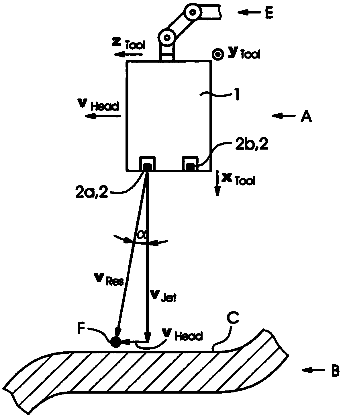
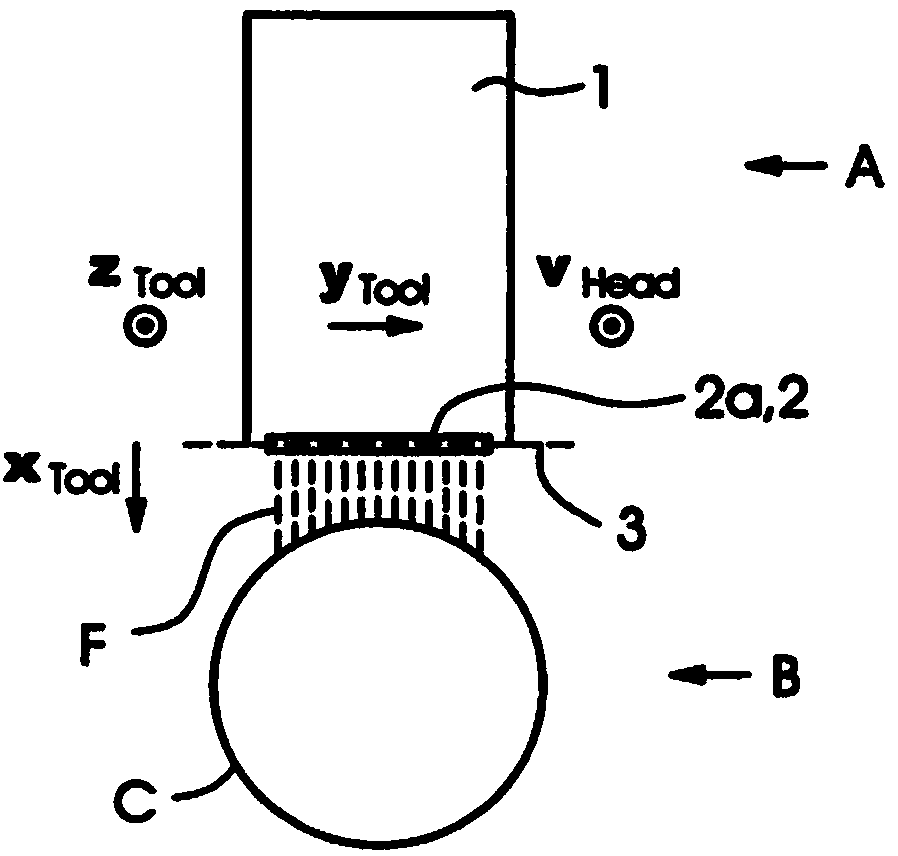
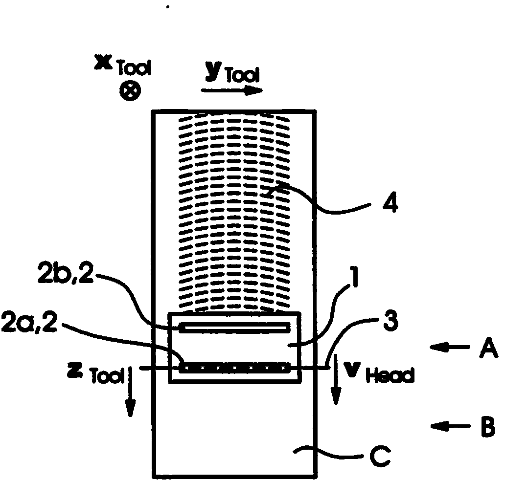
[0042] Figure 1A shows a side view of a device A with an inkjet print head 1 printing on a curved surface C of an object B, eg a tube. The print head has two nozzle rows 2a and 2b with corresponding inkjet nozzles 2 (better seen in FIG. 1B ). However, the printing head 1 can also have only one nozzle row or more than two nozzle rows.

[0043] The mutually orthogonal axes relative to the coordinate system fixed by the printing head (print head coordinate system) are indicated in the drawing by xTool, yTool and zTool. In a preferred embodiment, the inkjet print head A is moved by a robotic arm E for generating a relative velocity component between the print head A and the surface C. Here, the axes xTool, yTool and zTool can be understood as the axes of the tool coordinate system of the robotic arm E.

[0044] The speed and direction of movement (forward movement or main movement) of the printing head A during printing is indicated in the figure by the vector vHead. When print...


PUM


Abstract

An apparatus for printing on a curved surface of an object through an ink jet print head, eg., on a motor vehicle body, wherein the print head (1) at least one nozzle row (2a, 2b) with nozzles (2) for ejecting ink -drops (F), and wherein the print head (1) and / or the object (B) of a moving device (E), preferably a 6-axis robot, to produce a relative velocity component (VHEAD) between the print head (1) and surface (C) is moved, is characterized in that the print head (1) and / or the nozzle row (2a, 2b) to a to the nozzle row (2a, 2b) parallel to the axis (3) by an angle ([beta] ) against the direction of the relative velocity component (VHEAD) between the print head (1) and surface (C), ie; is against the forward movement inclined such that ejected ink drop (F), a relative speed component (vJetZ) between drops (F) and the surface (C) obtained by the relative velocity component (VHEAD) between the print head (1) and surface (C) is substantially compensated. Speed-dependent print image distortions can be reduced or avoided in an advantageous manner without changing the print image data.

Description

technical field [0001] The invention relates to a device for printing on curved surfaces of objects with an inkjet printing head, having the features stated in the preamble of claim 1 . Furthermore, the invention relates to a method for printing on curved surfaces of objects with an inkjet print head, having the features stated in the preamble of claim 9 . [0002] The present invention is in the technical field of inkjet printing or inkjet printing. Background technique [0003] It is known to paint objects with free-form surfaces, for example vehicle bodies, either monochrome or polychrome. The multi-coloured painting can be realized already in production or subsequently. It is also known that the bodywork is equipped with colorful graphics. For example, advertisements are placed on the side or rear of the vehicle. [0004] Prior art known in this technical field includes the following: [0005] DE 37 37 455 A1 discloses a device for producing color samples. With the...

Claims


Application Information

Patent Timeline
Patent Type & Authority Applications(China)
IPC IPC(8): B41J2/01B41J3/407
CPCB41J3/4073B41J25/316
Inventor M·内尔
Owner HEIDELBERGER DRUCKMASCHINEN AG
Why Eureka
Try Eureka