Carrying trolley for large-size oil cylinder

A kind of trolley and oil cylinder technology, applied in the direction of lifting device, etc., to achieve the effect of simple structure, manpower saving and easy handling

Inactive Publication Date: 2014-12-24
ANQING TIANRUN ENG MACHINERY
6 Cites 11 Cited by

AI-Extracted Technical Summary

Problems solved by technology

[0004] The technical problem to be solved by the present invention is to provide a small trolley for transp...

Method used

When moving goods, push the front fork 6 on the trolley below the oil cylinder, allow the piston rod of the oil cylinder to be positioned above the groove 7, press the V-shaped push rod 3 downwards, lift the oil cylinder by the principle of leverage, and move backwards Drag the trolley to separate the oil cylinder from the shelf, loosen the V-shaped push rod 3, th...

Abstract

The invention discloses a carrying trolley for a large-size oil cylinder and belongs to the field of manpowered transporting tool. The carrying trolley comprises a chassis, a lifting frame, a V-shaped push rod, a connecting rod, a handle and a front fork, wherein the lifting frame and the chassis are in the same shape; the lifting frame is located above the chassis; the V-shaped push rod comprises a short edge and a long edge; the short edge and the connecting rod are in the same length; the corresponding positions on the lifting frame and the chassis are connected by the connecting rod and the short edge of the V-shaped push rod; a rhomboid structure is formed by side walls; the handle is fixed on the long edge of the V-shaped push rod; the front fork is fixed at the front end of the lifting frame. The lever principle is applied to the trolley, so that the large-size oil cylinder can be easily lifted and moved to a destination. The structure is simple and the manpower is saved.

Application Domain

Technology Topic

Image

  • Carrying trolley for large-size oil cylinder
  • Carrying trolley for large-size oil cylinder

Examples

  • Experimental program(1)

Example Embodiment

[0016] In order to easily understand the technical means, creative features, purpose and effect of the present invention, the present invention will be further explained in conjunction with specific drawings below.
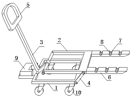
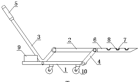
[0017] Such as figure 1 , figure 2 As shown, a large oil tank carrying trolley includes a base frame 1, a lifting frame 2, a V-shaped push rod 3, a connecting rod 4, a handle 5, and a front fork 6. The lifting frame 2 has the same shape as the base frame 1, which is lifted The frame 2 is located above the base frame 1. The V-shaped push rod 3 is divided into a short side and a long side. The short side has the same length as the connecting rod 4. The short side of the connecting rod 4 and the V-shaped push rod 3 will lift the frame 2 and the base 1 The upper corresponding positions are connected and form a parallelogram structure from the side. The handle 5 is fixed on the long side of the V-shaped rod 3, and the front fork 6 is fixed on the front end of the lifting frame 2. A number of pairs of grooves 7 are provided on the front fork 6 and rubber pads 8 are provided in the grooves 7. A counterweight box 9 is provided at the rear of the underframe 1. The chassis 1 is provided with four universal wheels 10.
[0018] When moving goods, push the front fork 6 on the trolley into the bottom of the cylinder, so that the piston rod of the cylinder is above the groove 7, press the V-shaped push rod 3 downward, tilt the cylinder through the principle of leverage, and drag the cylinder backwards. Push the cart to remove the oil cylinder from the shelf, loosen the V-shaped push rod 3, and the oil cylinder falls on the bottom frame 1 with the lifting frame 2 and drag the small cart to complete the transportation. The function of the counterweight box 9 is that the oil cylinder does not fall on the center of gravity of the trolley, and the counterweight box 9 needs to be used to balance the trolley to make the transportation more stable.
[0019] The basic principles and main features and advantages of the present invention have been shown and described above. Those skilled in the industry should understand that the present invention is not limited by the above-mentioned embodiments. Without departing from the spirit and scope of the present invention, the present invention will have various changes and improvements, and these changes and improvements fall under the protection of the claims. Within the scope of the present invention. The scope of protection claimed by the present invention is defined by the appended claims and their equivalents.

PUM

no PUM

Description & Claims & Application Information

We can also present the details of the Description, Claims and Application information to help users get a comprehensive understanding of the technical details of the patent, such as background art, summary of invention, brief description of drawings, description of embodiments, and other original content. On the other hand, users can also determine the specific scope of protection of the technology through the list of claims; as well as understand the changes in the life cycle of the technology with the presentation of the patent timeline. Login to view more.

Similar technology patents

Classification and recommendation of technical efficacy words

  • Simple structure
  • Save human effort

Beam expanding optical element, beam expansion method, image display apparatus, and head-mounted display

InactiveUS20070188837A1Reduce color unevennessSimple structureOptical light guidesSubstrate with hologramHead worn displayLight wave
Owner:KONICA MINOLTA INC

Microlithographic projection exposure apparatus

InactiveUS20050068499A1Simple structureReliable and low-maintenance operationProjectorsPhotomechanical exposure apparatusCamera lensPhysics
Owner:CARL ZEISS SMT GMBH
Why Eureka
Try Eureka