
Pressure storage type efficient and energy-saving excavator

A high-efficiency, energy-saving, excavator technology, applied in the direction of earth mover/shovel, construction, etc., can solve the problems of unfavorable excavator energy-saving engineering cost reduction, increase excavator oil consumption, unstable output power and other problems, and achieve optimization work. The effect of load, simple structure and continuous and stable pressure

Inactive Publication Date: 2014-12-24
杨皓捷
View PDF7 Cites 0 Cited by
  • Summary
  • Abstract
  • Description
  • Claims
  • Application Information

AI Technical Summary

Problems solved by technology

[0002] Excavator is one of the large-scale construction machinery commonly used in the engineering field. It has good adaptability to the working environment and high work efficiency. The current excavator generally adopts hydraulic form. Hydraulic excavator is mainly composed of engine, hydraulic system, working device, traveling device and The hydraulic system consists of hydraulic pumps, control valves, hydraulic cylinders, hydraulic motors, pipelines, fuel tanks, etc. The working device is a device that directly completes the excavation task. It consists of booms, sticks, and buckets. It is partly hinged, and the lifting of the boom, the expansion and contraction of the arm and the rotation of the bucket are all controlled by reciprocating double-acting hydraulic cylinders. The hydraulic power is to use the hydraulic transmission system to transmit the power of the engine to the hydraulic motor and hydraulic cylinder through the hydraulic pump. The components push the working device to move, so as to complete various operations. In this working mode, the provision of hydraulic power requires the engine to continuously drive the hydraulic pump. During work, the output power of the engine needs to change continuously according to the needs of the working device, and the output power does not vary. Stable, the engine speed cannot be well stabilized near the most fuel-efficient value. For example, when a large hydraulic pressure is required, the engine needs to output a large power, and the energy consumption will increase significantly. When the engine is idling, it still needs to consume energy. Due to excavation The excavator itself is a construction machine that consumes a lot of fuel. The excavator in this working mode will increase the fuel consumption of the excavator, which is not conducive to the energy saving of the excavator and the reduction of engineering costs.

Method used


Image

  • Pressure storage type efficient and energy-saving excavator

Examples


Embodiment Construction

[0007] In order to more fully explain the implementation of the present invention, implementation examples of the present invention are provided. These implementation examples are only illustrations of the device and do not limit the scope of the present invention.

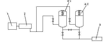
[0008] as attached figure 1 As shown, a pressure storage type high-efficiency energy-saving excavator includes an engine 1 and a hydraulic pump 2. The excavator is provided with a hydraulic pressure accumulator, and the engine 1 drives the hydraulic pump 2 to be hydraulically stored in the hydraulic pressure accumulator through the pipeline. The hydraulic pressure accumulator drives the hydraulic actuator through the pipeline. There are at least two hydraulic pressure accumulators. The hydraulic actuator includes a hydraulic cylinder and a hydraulic motor. 3 shows a hydraulic cylinder. The hydraulic pressure accumulator A pressure sensor is arranged in the pressure accumulator, and the pressure sensor transmits t...


PUM


Abstract

The invention relates to an energy-saving excavator, and belongs to the field of engineering machinery. The excavator comprises an engine and a hydraulic pump. A hydraulic pressure storage device is arranged in the excavator. The engine drives the hydraulic pump to store hydraulic pressure to the hydraulic pressure storage device through a pipeline. The hydraulic pressure storage device drives a hydraulic execution element through a pipeline. The energy-saving excavator is simple in structure, the elements can be easily obtained, the energy-saving excavator can be conveniently applied to engineering machines such as excavators, oil consumption can be remarkably lowered, engineering cost can be remarkably reduced, and the energy-saving excavator is an environment-friendly engineering machine.

Description

technical field [0001] The invention relates to an excavator, in particular to an energy-saving excavator, which belongs to the field of engineering machinery. Background technique [0002] Excavator is one of the large-scale construction machinery commonly used in the engineering field. It has good adaptability to the working environment and high work efficiency. The current excavator generally adopts hydraulic form. Hydraulic excavator is mainly composed of engine, hydraulic system, working device, traveling device and The hydraulic system consists of hydraulic pumps, control valves, hydraulic cylinders, hydraulic motors, pipelines, fuel tanks, etc. The working device is a device that directly completes the excavation task. It consists of booms, sticks, and buckets. It is partly hinged, and the lifting of the boom, the expansion and contraction of the arm and the rotation of the bucket are all controlled by reciprocating double-acting hydraulic cylinders. The hydraulic pow...

Claims


Application Information

Patent Timeline
Patent Type & Authority Applications(China)
IPC IPC(8): E02F9/20E02F9/22
Inventor 杨皓捷
Owner 杨皓捷
Learn More