Stay wire binding tool

A tool and bar-shaped technology, applied in the field of wire binding tools, can solve problems such as damage to the galvanized layer of the iron wire, easy burrs to hurt people, and non-conformity of the wire, so as to achieve a convenient structure that is not easy to hurt hands, easy to operate and carry, and has a reasonable structure. Effect

Active Publication Date: 2014-12-24
STATE GRID CORP OF CHINA +2
View PDF6 Cites 4 Cited by
  • Summary
  • Abstract
  • Description
  • Claims
  • Application Information

AI Technical Summary

Problems solved by technology

Generally, the operation process of making the cable nose and connecting the upper, middle and lower handles is called "drawing the cable". Tighten the iron wire with a hammer. This traditional method of binding the wire with pliers needs to be wound slowly. The arrangement of the wires for winding and binding is not uniform. This method of binding the wire is not only time-consuming and laborious, but also damages the galvanized layer of the wire. Moreover, the guy wires made do not meet the requirements of the "Code for Construction and Acceptance of Overhead Power Lines"; during operation, operators are easily pulled out of deep grooves or burrs by wire cutters and easily hurt people

Method used


Image

  • Stay wire binding tool
  • Stay wire binding tool
  • Stay wire binding tool

Examples


Embodiment 1

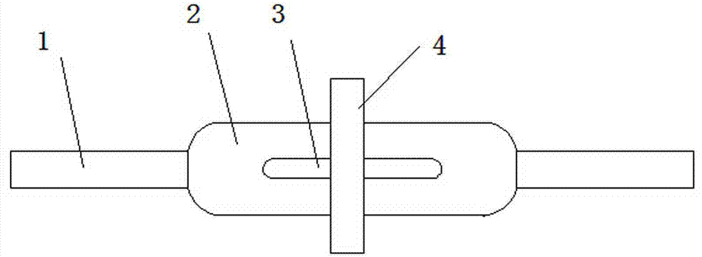
[0021] See figure 1 , figure 2 , The tool includes a strip-shaped plate body 2, the middle part of the strip-shaped plate body 2 is provided with a long strip hole 3, and the two ends of the strip-shaped plate body 2 are provided with handles 1 in the length direction; The guide post 4 for changing the direction of the iron wire, wherein the guide post 4 and the strip-shaped plate body 2 are arranged separately. When in use, the guide post 4 and the elongated hole 3 are arranged in a crisscross pattern. The guide post 4 can be an ordinary 10 ×100 bolts are sufficient. There is a rubber sleeve on the handle 1, and the rubber sleeve has a friction pattern, which not only makes the operator comfortable to hold and prevents scratches, but also increases the friction and makes the operation more labor-saving.

[0022] The length of the handle 1 is 80-120mm and the diameter is 15-25mm; the length of the strip-shaped plate body 2 is 120-180mm; the length of the guide post 4 is 50-100mm...

Embodiment 2

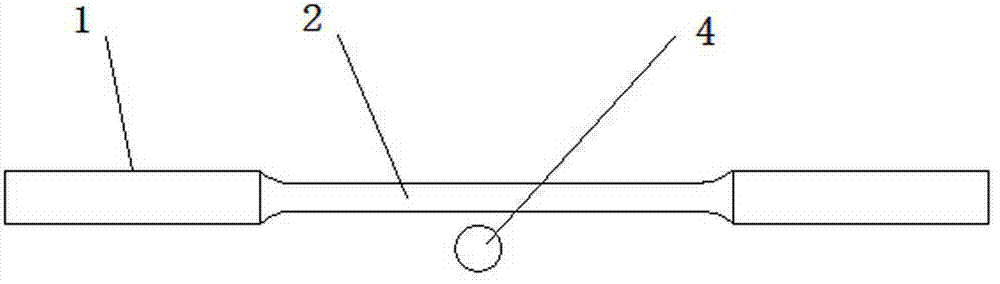
[0025] See Figure 4 The difference between this embodiment and the first embodiment is: on one side of the strip-shaped plate body 2, two ear holes 5 are fixed, and the two ear holes 5 are distributed on both sides of the elongated hole 3; the guide post 4 It can pass through the two ear holes 5 and is perpendicular to the elongated hole 3. When in use, the guide post 4 is inserted into the ear hole 5, the iron wire is passed around the guide post 4, and the handle 1 is held with both hands, so that the strip plate 2 closes to the outer circle of the cable, and the iron wire is tightly wound on the cable.

Embodiment 3

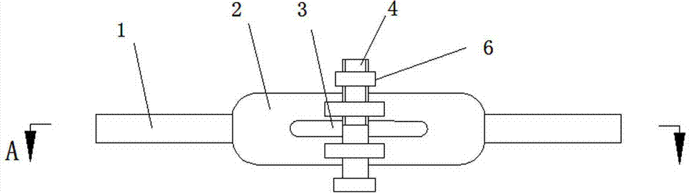
[0027] See image 3 , Figure 4 The guide post 4 is a bolt, and one end of the bolt is equipped with a nut 6, and the bolt is inserted into the ear hole 5, and the nut 6 is screwed on, so that the bolt will not fall, which is convenient to carry and prevents the guide post 4 from being lost.

[0028] The structure of the tool is more reasonable, lighter and more convenient to use; the tool can be used to fast, accurately and tightly bind the wire to the cable, which greatly improves the work efficiency of the cable binding and reduces the labor intensity; at the same time, it will not hurt The galvanized layer of the cable and the operator. This tool is a very simple and practical cable lashing tool.


PUM


Abstract

The invention discloses a stay wire binding tool, and relates to the technical field of electric transmission line construction. The stay wire binding tool comprises a strip-shaped plate, a long hole is formed in the middle of the strip-shaped plate, and handles are arranged at the two ends of the strip-shaped plate in the length direction. A guide column used for changing the direction of an iron wire in the stay wire binding process is further included. The stay wire binding tool is simple in structure and convenient to use, time and labor are saved, the iron wire can be bound on the stay wire fast, accurately and densely, the work efficiency of stay wire binding is greatly improved, and labor intensity is reduced. Meanwhile, the zinc coating of the stay wire cannot be damaged, and operating personnel cannot be hurt.

Description

Technical field [0001] The invention relates to the technical field of power transmission line construction, in particular to a cable binding tool. Background technique [0002] In the construction of the power supply line, the load-bearing poles such as swelling resistance, corners, branches, terminals and spans must be tied to the cables to balance the force of the poles and ensure the stability of the line. High and low voltage overhead distribution lines generally use galvanized steel stranded wire as the pull wire. The manufacturing process of the pull wire is to first bend the end of the pull wire and fold it in half, and then use the steel wire to tightly wrap the head of the bent part. Generally, the process of making the cable nose and connecting the upper, middle and lower handles is called "pull-up". In the process of making the cable, wire pliers are usually used to fasten the wire on the stranded wire, and then use Hammer smashes the wire. This traditional method of...

Claims


Application Information

Patent Timeline
Patent Type & Authority Applications(China)
IPC IPC(8): E04H12/20
Inventor 马文平
Owner STATE GRID CORP OF CHINA
Why Eureka
Try Eureka