
Demountable impeller

A detachable, impeller technology, used in non-variable volume pumps, parts of pumping devices for elastic fluids, machines/engines, etc. problems, to achieve the effect of stable operation, easy promotion and use, and reasonable structure

Inactive Publication Date: 2014-12-24
SHANGHAI HEHUA ELECTRONICS TECH
View PDF1 Cites 2 Cited by
  • Summary
  • Abstract
  • Description
  • Claims
  • Application Information

AI Technical Summary

Problems solved by technology

[0002] With the development of social production and the rapid development of the machinery industry, a large number of industrial tools are produced and used. With the extensive development of the manufacturing industry, the role of the impeller in industrial operations cannot be ignored. The application number is CN 201010106104.2, which discloses a detachable Type impeller, including the wheel body, a vortex chamber is set in the wheel body, the vortex chamber inlet is set in the middle of the vortex chamber, and a plurality of guide vanes are arranged around the vortex chamber. The angle between the guide vanes and the radius of the wheel body is A1, and the angle range of A1 is greater than 0 degrees and less than 90 degrees, the impeller makes full use of circular motion and fluid motion, using the vortex with increasing speed from the center to the periphery to make the fluid automatically sucked into the vortex from the center of the vortex, using the center of the vortex to generate suction, and using the vortex to increase the pressure and linear velocity of the fluid for the first time , using the guide vane angle and the contraction of the fluid channel to further increase the fluid linear velocity and pressure, using the groove body on the outer edge of the impeller to further promote the improvement of the fluid linear velocity by the impeller, and using the vortex formed on the periphery of the impeller to decrease in speed from the center to the periphery. The periphery of the impeller generates high pressure, which can widely replace the impellers of existing water pumps, fans, compressors, suction equipment, spray equipment, etc., which can save energy, reduce noise, improve service life, and reduce equipment cost, but the blades of the impeller are not removable , when one of the blades is damaged, it cannot be replaced individually, it needs to be replaced as a whole, which wastes resources, and the blades are easy to fall off, and the impeller runs unstable

Method used


Image

  • Demountable impeller
  • Demountable impeller

Examples


Embodiment Construction

[0013] In order to make the technical means, creative features, goals and effects achieved by the present invention easy to understand, the present invention will be further described below in conjunction with specific illustrations.

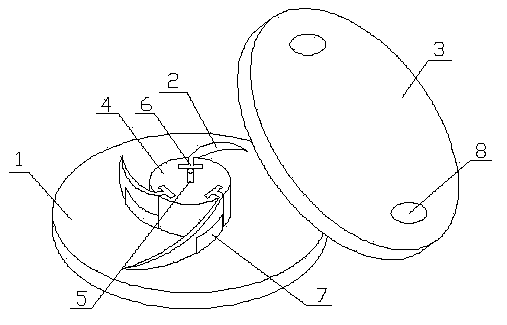
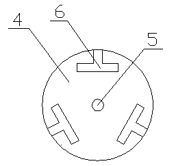
[0014] Such as figure 1 and figure 2 As shown, the detachable impeller of the present invention includes a hub 1, blades 2 and a cover plate 3, the hub 1 is provided with a central column 4, the central column 4 is provided with a connecting rod 5, and the center The column 4 is connected with the cover plate 3 through the connecting rod 5, the central column 4 is provided with a groove 6, the blade 2 is connected with the central column 4 through the groove 6, and the blade 2 on the hub 1 is fixed with a stopper. Plate 7, the baffle 7 is connected to the blade 2, the shape of the connection between the baffle 6 and the blade 2 is the same as that of the blade 2, and the blade is connected to the central column through a groove, so that the bl...


PUM


Abstract

The invention discloses a demountable impeller comprising a hub, blades and a cover disc. A center post is arranged on the hub. A connecting rod is arranged on the center post. The center post is connected with the cover disc through the connecting rod. The center post is provided with grooves. The blades are connected with the center post through the grooves. Retainer boards are fixed to the hub at the blades and are connected with the blades. The connections of the retainer boards and the blades are in the same shapes as the blades; the blades are connected with the center post through the grooves so that the blades are demountable. When damaged, one blade can be independently replaced; overall replacement is not required; resources are saved; the structure is reasonable. The retainer boards ensure that shedding of the blades is prevented when the impeller runs; the impeller runs stably; the impeller is handy and convenient to polarize and apply.

Description

technical field [0001] The invention relates to the field of industrial machinery, in particular to a detachable impeller. Background technique [0002] With the development of social production and the rapid development of the machinery industry, a large number of industrial tools are produced and used. With the extensive development of the manufacturing industry, the role of the impeller in industrial operations cannot be ignored. The application number is CN 201010106104.2, which discloses a detachable Type impeller, including the wheel body, a vortex chamber is set in the wheel body, the vortex chamber inlet is set in the middle of the vortex chamber, and a plurality of guide vanes are arranged around the vortex chamber. The angle between the guide vanes and the radius of the wheel body is A1, and the angle range of A1 is greater than 0 degrees and less than 90 degrees, the impeller makes full use of circular motion and fluid motion, using the vortex with increasing spee...

Claims


Application Information

Patent Timeline
Patent Type & Authority Applications(China)
IPC IPC(8): F04D29/22
Inventor 郑小坚郭炎铭
Owner SHANGHAI HEHUA ELECTRONICS TECH
Learn More