Soil evaporation capacity monitoring method in cracked coal mining subsidence area
A technology of soil evaporation and coal mining subsidence area, which is applied in the direction of soil material testing, material inspection, etc., can solve the problems of accelerated soil water loss, different shapes, and increased evaporation area
- Summary
- Abstract
- Description
- Claims
- Application Information
AI Technical Summary
Problems solved by technology
Method used
Image
Examples
Embodiment 1
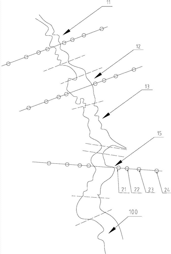
[0021] Embodiment 1 is aimed at the bare land without plants on the ground, and the crack 100 is a single crack. exist figure 1 In the diagram, broken lines are used to represent the segmentation of the crack 100. For the sake of simplicity in the drawing, only the narrow crack segment 11, the wide crack segment 12 and the middle crack segment 13 are selected, and each segment is marked. figure 1 The straight line perpendicular to the direction of the fracture is the straight line used to set the monitoring point, and the small circle in it represents the monitoring point, and the micro-evaporator is set at this position. It should be noted that since cracks are generally irregular, vertical here refers to a direction roughly perpendicular to the crack at the selected monitoring point.
[0022] like figure 1 As shown, embodiment one of the present invention has the coal mining subsidence area soil evaporation monitoring method of crack, comprises the steps:
[0023] (1) Div...
Embodiment 2
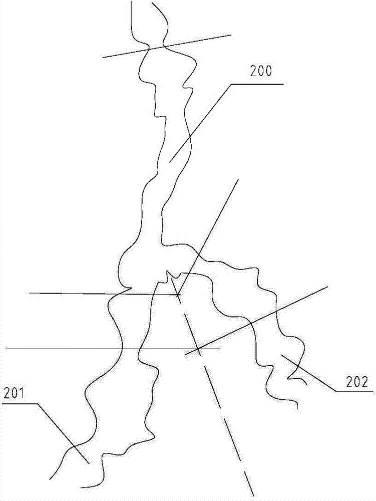
[0036] figure 2 It is a schematic diagram of the arrangement of monitoring points in Embodiment 2 of the present invention, figure 2 Monitoring points are omitted in . like figure 2 As shown, the difference between the second embodiment and the first embodiment is that the crack 200 bifurcates and is divided into a first crack 201 and a second crack 202. The setting method of the monitoring points on the first crack 201 and the second crack 202 is also the same as that of the first embodiment. However, since the first crack 201 and the second crack 202 are opposite, the monitoring points between the two are set opposite to each other, and finally meet at the center line of the two, that is, figure 2 near the dotted line in .
[0037] In addition, due to the existence of forks, such as figure 2 As shown in , monitoring points are also set at the bifurcation of cracks. That is, the intersections of the slit 200, the first slit 201 and the second slit 202 are set. The...
Embodiment 3
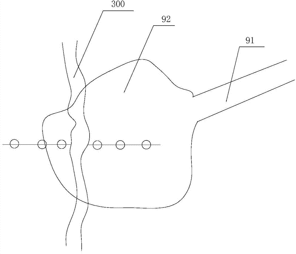
[0039] image 3 It is a schematic diagram of the arrangement of monitoring points in Embodiment 3 of the present invention (when cracks pass through the projected area). like image 3 As shown, in the third embodiment, the crack 300 passes through the projected area of the plant, in image 3 In the figure, for the sake of brevity, no plants are shown, only the shadow 91 of the trunk and the shadow 92 of the crown are shown, and the crack 300 passes through the shadow 92 of the crown. Considering the influence of plants on evaporation, when selecting monitoring points, a monitoring point is added at a section where the crack 300 passes through the projection area. The projection area of plants refers to the union of the shadow areas of plants in one day. The distance and number of monitoring points are the same as those of the no-shade area, but a column of monitoring points is added in the projection area to reflect the interaction of plant cracks. Dynamic influence of ...
PUM
 Abstract
Description
Claims
Application Information
 - R&D
- Intellectual Property
- Life Sciences
- Materials
- Tech Scout
- Unparalleled Data Quality
- Higher Quality Content
- 60% Fewer Hallucinations
Browse by: Latest US Patents, China's latest patents, Technical Efficacy Thesaurus, Application Domain, Technology Topic, Popular Technical Reports.
© 2025 PatSnap. All rights reserved.Legal|Privacy policy|Modern Slavery Act Transparency Statement|Sitemap|About US| Contact US: help@patsnap.com


