Textile Drying Rate Tester

A drying rate, textile technology, applied in the field of testing machines, can solve the problems of low testing efficiency, frequent operation, low efficiency and so on

Active Publication Date: 2016-06-29
SHENZHEN REFOND EQUIP CO LTD
View PDF6 Cites 0 Cited by
  • Summary
  • Abstract
  • Description
  • Claims
  • Application Information

AI Technical Summary

Problems solved by technology

There are errors in the existing manual testing methods, and the testing efficiency is low. For example, when a group of tests is in progress, the staff needs to operate frequently, and the efficiency is low.

Method used


Image

  • Textile Drying Rate Tester

Examples


Embodiment Construction

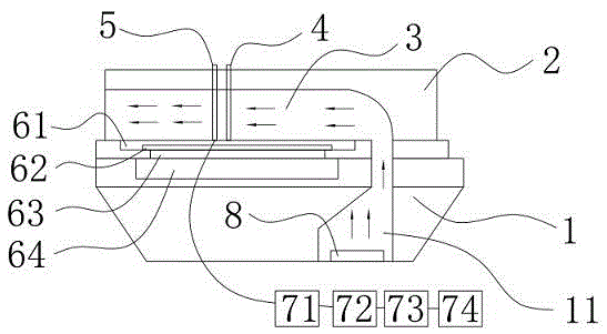
[0024] Such as figure 1 In the shown textile drying rate testing machine, the upper cover 2 and the base 1 are combined to form a drying chamber 3 for air circulation; a heating plate 62 for providing heat is installed on the side of the base 1 close to the drying chamber 3; Covering the heat conduction plate 61, the heat conduction plate 61 is used to transfer heat to the textile evenly and quickly; the water outlet of the pump 72 is installed on the upper surface of the heat conduction plate 61, and the pump 72 is used to remove the test water from the heat conduction plate 61; the water injection electromagnetic The valve 71 is installed on the outlet pipeline of the pump 72, and the water injection solenoid valve 71 is used to control the flow and timing of the pump 72 delivering water; the water outlet of the pump 72 is equipped with a temperature sensor 5, and the temperature sensor 5 is used to detect the temperature of the textile. The textile drying rate testing machi...


PUM


Abstract

The invention belongs to the field of testing machines, in particular to a testing machine for testing the drying speed of textiles. The combination of the upper cover and the base forms a drying chamber for air circulation; a heating plate for providing heat is installed on the side of the base close to the drying chamber; the heating plate is covered with a heat conducting plate, which is used to transfer heat evenly and quickly to the Textiles; the water outlet of the pump is installed on the upper surface of the heat conduction plate, and the pump is used to send test water to the heat conduction plate; the water injection solenoid valve is installed on the water outlet pipeline of the pump, and the water injection solenoid valve is used to control the flow and timing of the water delivered by the pump ; A temperature sensor is installed at the water outlet of the pump, and the temperature sensor is used to detect the temperature of the textile. The textile drying rate testing machine simulates the temperature of the human body through the heating plate and the heat transfer plate. At the same time, the test water is passed into the textile through the pump and the temperature of the textile is detected through the temperature sensor, so that the textile drying speed test is completely automated.

Description

technical field [0001] The invention belongs to the field of testing machines, in particular to a testing machine for testing the drying speed of textiles. Background technique [0002] The textile drying rate test adopts the American AATCC201-2013 standard. The usual method is manual operation. The fabric surface has a horizontal airflow of 1.5 m / s generated by a vertical bellows and a guide plate. The fabric surface temperature is passed through a non-contact infrared temperature sensor. To measure, the airflow velocity is monitored by a hot-wire anemometer. During the test, a fabric sample needs to be placed on a hot plate with a constant temperature of 37°C, 0.200±0.003mL of water is dropped on the hot plate under the center of the fabric, and the temperature change of the fabric is monitored. [0003] The current test method is to lift the fabric on one side, cover the fabric immediately after water drips from the center of the hot plate and start timing. A temperatur...

Claims


Application Information

Patent Timeline
Patent Type & Authority Patents(China)
IPC IPC(8): G01N33/36
Inventor 巫班金
Owner SHENZHEN REFOND EQUIP CO LTD
Why Eureka
Try Eureka