
End face processor adjusting structure

A technology of adjusting structure and processor, applied in the direction of coupling of optical waveguides, etc., can solve the problems of increasing the diameter of the fiber end face, time-consuming and laborious, affecting the optical performance of the connector, etc., to achieve the effect of convenient installation and accurate alignment

Active Publication Date: 2014-12-24
JIANGSU UNIKIT OPTICAL TECH
View PDF6 Cites 2 Cited by
  • Summary
  • Abstract
  • Description
  • Claims
  • Application Information

AI Technical Summary

Problems solved by technology

[0002] There is always a cutting plane in the fiber optic field connector, which affects the optical performance of the connector. Although most manufacturers currently use fiber optic refractive index matching fluid to make up for it, the fiber optic refractive index matching fluid is a liquid substance, which is easy to be polluted and easily lost. To a large extent, it affects the stability and reliability of the optical fiber field connector. The requirement for further spherical processing of the fiber cut end face eliminates the time-consuming and laborious method of grinding. In view of the fact that ordinary optical fibers are made of quartz, their properties are not good at high temperatures. Due to the changing characteristics, it was decided to adopt high-temperature melting and use the surface tension of the liquid to shrink into a spherical surface to achieve the goal of this project. It fully used the arc generation technology of the optical fiber fusion splicer to produce an instantaneous melting of the optical fiber end face at over 2000°C, but due to the surface tension Shrinkage causes the fiber endface diameter to increase while the endface is spherical and cannot be assembled through a ceramic ferrule

Method used


Image

  • End face processor adjusting structure
  • End face processor adjusting structure
  • End face processor adjusting structure

Examples


Embodiment Construction

[0023] Below in conjunction with accompanying drawing, the present invention is described in further detail:

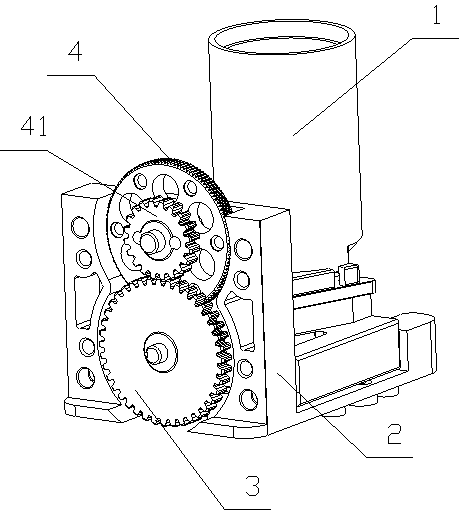
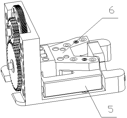
[0024] As shown in the figure: the adjustment structure of the end surface treatment machine includes a magnifying glass seat 1, a sliding table seat 2, and a sliding table; the magnifying glass seat 1 is arranged on the sliding table, and the sliding table is arranged on the sliding table seat 2; Swipe up.

[0025] The slide base 2 is L-shaped, and the vertical end surface of the slide base 2 has a transmission gear 3 and a rotary pulley 4; the rotary pulley 4 is provided with a coaxial small transmission tooth 41; . The axle center of transmission gear 3 is provided with screw rod, and screw rod links to each other with slide table.

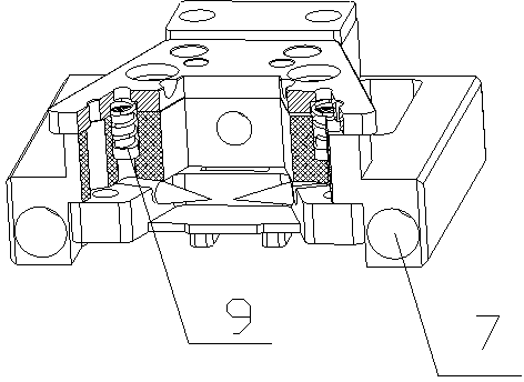
[0026] The slide table includes: a bottom slide table 5, a connecting slide table 6, and a needle cover 8; the needle cover 8 is arranged inside the bottom slide table 5; the top end of the bottom slide table 5 is provided with a con...


PUM


Abstract

The invention relates to an end face processor adjusting structure, and belongs to the field of optical fiber cold connection equipment. The end face processor adjusting structure comprises a magnifying glass base, a sliding table base and a sliding table. The magnifying glass base is arranged on the sliding table, and the sliding table is arranged on the sliding table base. The sliding table slides on the sliding table base. According to the end face processor adjusting structure, the size, an operation button and the appearance of an original product are changed, the structure is suitable for the operation habits of constructors, and the structure is more convenient and faster to mount. The adjusting device is additionally arranged based on the original product, and the product end face is aligned by adjusting the distance of electrodes. Microcosmic sliding of the distance of the electrodes is achieved by manual macroscopic adjusting and rotating through the linkage adjusting device, and thus the end face of the product can be accurately aligned.

Description

technical field [0001] The invention relates to an adjustment structure of an end face processor, which belongs to the field of optical fiber cold connection equipment. Background technique [0002] There is always a cutting plane in the fiber optic field connector, which affects the optical performance of the connector. Although most manufacturers currently use fiber optic refractive index matching fluid to make up for it, the fiber optic refractive index matching fluid is a liquid substance, which is easy to be polluted and easily lost. To a large extent, it affects the stability and reliability of the optical fiber field connector. The requirement for further spherical processing of the fiber cut end face eliminates the time-consuming and laborious method of grinding. In view of the fact that ordinary optical fibers are made of quartz, their properties are not good at high temperatures. Due to the changing characteristics, it was decided to adopt high-temperature melting ...

Claims


Application Information

Patent Timeline
Patent Type & Authority Applications(China)
IPC IPC(8): G02B6/255
Inventor 黄金安谢小波吴存奶邱向前刘德伟王胜楠崔青卓
Owner JIANGSU UNIKIT OPTICAL TECH
Learn More