Complicated surface cutting force prediction method and parameter adjustment and tool path planning method

A complex profile and cutting force technology, which is used in parameter adjustment and tool path planning, predicting the magnitude of cutting force during complex profile turning, and can solve the problems of complex calculation of irregular geometric areas and many types of contact areas.

Active Publication Date: 2014-12-24
BEIJING INSTITUTE OF TECHNOLOGYGY
View PDF3 Cites 27 Cited by
  • Summary
  • Abstract
  • Description
  • Claims
  • Application Information

AI Technical Summary

Problems solved by technology

However, the existing methods for calculating the model parameters (cutting layer area and contact edge length, etc.) of the theoretical model of cutting force are mostly simple analytic geometric methods. For complex surface turnin...

Method used


Image

  • Complicated surface cutting force prediction method and parameter adjustment and tool path planning method
  • Complicated surface cutting force prediction method and parameter adjustment and tool path planning method
  • Complicated surface cutting force prediction method and parameter adjustment and tool path planning method

Examples


Embodiment Construction

[0039] The invention provides a method for predicting the magnitude of the cutting force during complex surface turning, including the establishment of the cutting force model, the division of the geometric type of the tool-workpiece contact area, the determination of the model parameter calculation method and the prediction process. The details are described below respectively.

[0040] Establishment of cutting force model

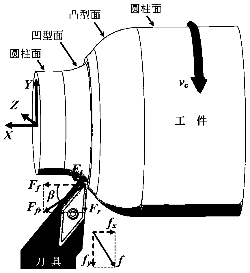
[0041] The cutting force is generated by the deformation of the material being cut and the friction between the tool and the workpiece. figure 1 Shown is the force on the tool during turning of typical complex surfaces (including cylindrical, concave and convex surfaces). Take the opposite direction of the axial feed of the tool as the X axis, along the cutting speed v c The direction perpendicular to the base plane of the tool is the Z axis, and the Y axis is determined by the right-hand rule. Under the coordinate system established here, the force can...


PUM


Abstract

The invention discloses a complicated surface cutting force prediction method and a method for performing parameter adjustment and tool path planning by use of the prediction method, and both the methods have generalizability and can be used for effectively reducing the model core parameter computation complexity and improving the effectiveness of an established complicated surface cutting force prediction model. The prediction method comprises the following steps: dividing a cutter-workpiece contact area into a type I only containing a cutter tip arc-shaped edge area and a type II containing a cutter tip arc-shaped area and a main cutting edge area according to the condition whether the outline of a to-be-processed surface is intersected with the arc-shaped edge or not; as for the type II containing the cutter tip arc-shaped area and the main cutting edge area, computing the total area of a cutting layer, the total length of the contact edge, the cutting layer area of the cutter tip arc-shaped edge area, the length of the contact edge and the direction angles of friction forces, obtaining correlation model parameters of the main cutting edge area by use of a subtractive method and weighting the direction angles of friction forces of the two areas, thereby obtaining the total friction force direction angle; as for the type I only containing the cutter tip arc-shaped edge area, computing the model parameters of the cutter tip arc-shaped edge area; substituting the computed model parameters into a cutting force theoretical model, thereby obtaining a cutting force predicted value.

Description

technical field [0001] The invention relates to the technical field of cutting force prediction, in particular to a method for predicting the magnitude of cutting force during complex surface turning, and a method for parameter adjustment and tool path planning using the prediction method. Background technique [0002] The processing profiles of modern mechanical products are mostly complex profiles and require one-time processing. Due to the drastic changes in cutting force, it is easy to cause workpiece deformation and accelerate tool wear and damage, which is not conducive to production automation. Therefore, the establishment of a cutting force prediction model suitable for complex surface turning can calculate the cutting force according to different cutting parameters in the process of part process decision-making, so as to warn the situation of large cutting force and adjust the cutting parameters or process. Revise. [0003] In the past, the modeling and prediction ...

Claims


Application Information

Patent Timeline
IPC IPC(8): G06F19/00G05B19/41
Inventor 焦黎王西彬谭方浩刘志兵解丽静梁志强周天丰罗智文余璐云
Owner BEIJING INSTITUTE OF TECHNOLOGYGY
Why Eureka
Try Eureka