High-voltage switch cabinet for electrification indicating of shell

A high-voltage switchgear and live indication technology, applied in the field of switchgear, can solve the problems of insufficient space and large space, and achieve the effects of low manufacturing cost, increased protection level, and increased scope of application

Inactive Publication Date: 2014-12-24
栗进波
View PDF4 Cites 2 Cited by
  • Summary
  • Abstract
  • Description
  • Claims
  • Application Information

AI Technical Summary

Problems solved by technology

[0006] The purpose of the present invention is to solve the problem of insufficient space or too much space in the compartments during the installation of electrical equipment caused by the fixed position of the partitions in the prior art, and to provide a compartment in the cabinet whose size can be adjusted and is easy to detect. A kind of high-voltage switchgear for indicating whether the shell is live or not

Method used


Image

  • High-voltage switch cabinet for electrification indicating of shell
  • High-voltage switch cabinet for electrification indicating of shell
  • High-voltage switch cabinet for electrification indicating of shell

Examples


Embodiment 1

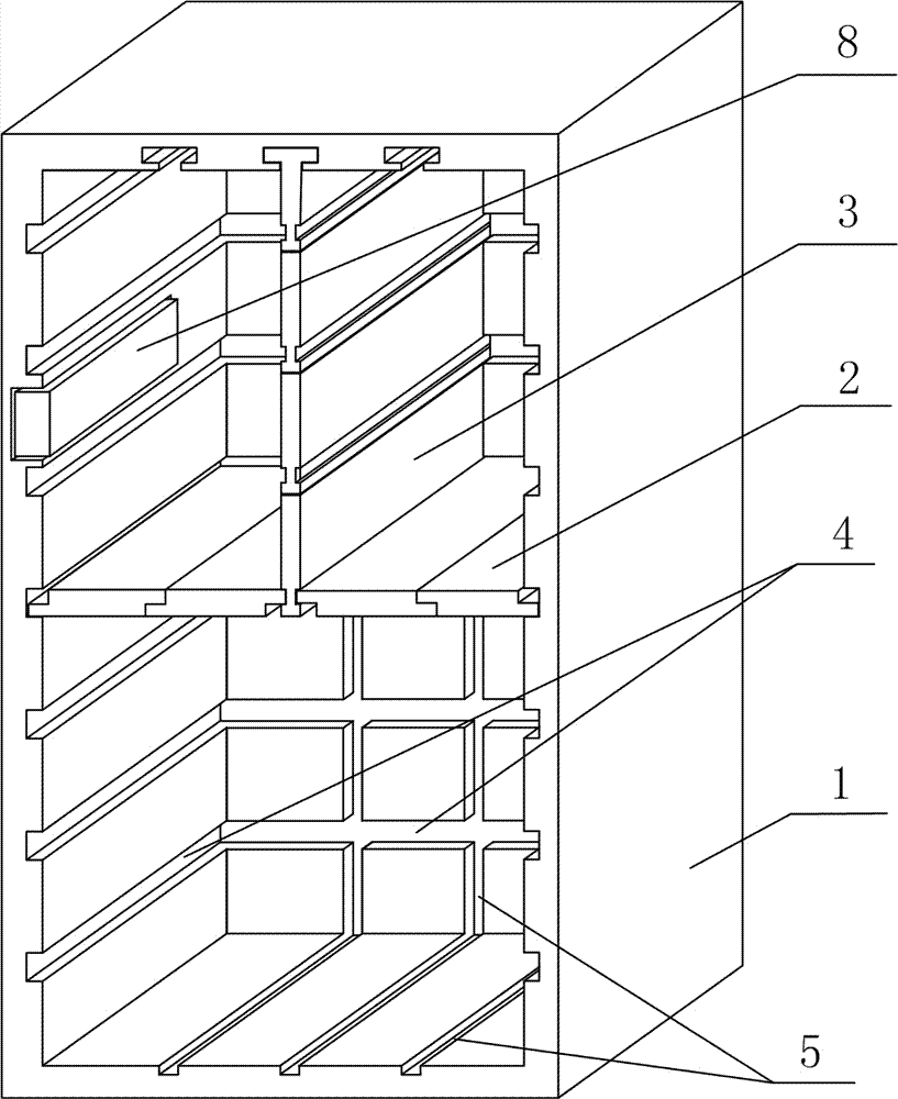
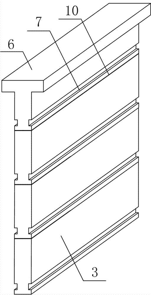
[0034] A high-voltage switchgear for indicating live electricity on the shell, such as figure 1 , image 3 with image 3 As shown, it includes a switch cabinet body 1, and a horizontal partition plate 2 and a vertical partition plate 3 arranged in the switch cabinet cabinet body 1; the inner wall of the switch cabinet body 1 is provided with a horizontal partition for placing the horizontal partition plate 2 Slot 4, the inner wall of the switchgear body 1 is also provided with a vertical placement groove 5 for placing the vertical partition 3; the cross section of the groove at the top of the vertical placement groove 5 is an inverted "convex" shape, and the vertical partition The top of the plate 3 is provided with a protruding piece 6 matching the inverted “convex” shape; the side wall of the vertical partition 3 is also provided with a connecting groove 7 corresponding to the position of the horizontally placed groove 4.

[0035] In order to detect whether there is a leakage of...

Embodiment 2

[0042] The difference between this embodiment and embodiment 1 lies in the optimization of the specific structures of the transverse partition 2 and the vertical partition 3, and the specific settings are as follows:

[0043] A broken crack 10 is also provided at a position 0.2-2 cm below the connecting groove 7 on the vertical partition 3. Through the setting of the broken crack 10, the height of the vertical partition 3 can be manually adjusted without any tools, thereby simplifying the operation steps.

[0044] The vertical placement grooves 5 are evenly distributed on the inner wall of the switch cabinet body 1, and the width of the transverse partition plate 2 is the same as the distance between two adjacent vertical placement grooves 5.

[0045] In the present invention, the number of vertical partitions 3 matching the number of vertical placement grooves 5 is configured, that is, when the number of vertical placement grooves 5 is N, the number of vertical partitions 3 is also ...

Embodiment 3

[0048] This embodiment further optimizes the setting method of the transverse partition 2 on the basis of the embodiment 2. The specific setting method is as follows:

[0049] The two ends of the transverse partition plate 2 are respectively provided with fasteners 11 for mutual cooperation, and the thickness of the fasteners 11 is the same as the height of the connecting groove 7. The depths of the connecting groove 7 and the horizontal placement groove 4 are h1 and h2, respectively, and the width of the fastener 11 is l, then l> h1, l> h2, l

[0050] Through the above arrangement, the stability of the present invention after installation is effectively increased.


PUM


Abstract

The invention discloses a high-voltage switch cabinet for electrification indicating of a shell and mainly solves the problem of insufficient space or overlarge space frequently occurring when a compartment is mounted due to the fact that partitions are fixed in position in the prior art. The high-voltage switch cabinet comprises a switch cabinet body, transverse partitions and vertical partitions, the transverse partitions and the vertical partitions are arranged in the switch cabinet body, horizontal placement grooves used for placement of the transverse partitions are formed in the inner wall of the switch cabinet body, vertical placement grooves used for placement of the vertical partitions are formed in the inner wall of the switch cabinet body, groove section at the top of each vertical placement groove is in the shape of an inverted Chinese character 'tu', a protruding member matched with the corresponding inverted 'tu' is arranged at the top end of each vertical partition, connecting grooves corresponding to the horizontal placement grooves in position are formed in the side wall of each vertical partition, and a medium-high-voltage electrification indicating circuit is connected on the switch cabinet body. The high-voltage switch cabinet has the advantages of adjustability in size of the compartment in the cabinet body, convenience in mounting, higher safety in operation and the like.

Description

Technical field [0001] The invention relates to a switch cabinet, and in particular to a high-voltage switch cabinet for shell live indication. Background technique [0002] The switch cabinet is a kind of electrical equipment. The outer line of the switch cabinet first enters the main control switch in the cabinet, and then enters the sub-control switch, and each branch is set according to its needs. Such as instrumentation, automatic control, motor magnetic switch, various AC contactors, etc., some also have high-voltage room and low-voltage room switch cabinets, high-voltage busbars, such as power plants, etc., and some also have low-cycle protection for main equipment Load shedding. [0003] The main function of the switchgear is to open and close, control and protect electrical equipment during the process of power generation, transmission, distribution and electrical energy conversion in the power system. The components in the switch cabinet are mainly composed of circuit b...

Claims


Application Information

Patent Timeline
Patent Type & Authority Applications(China)
IPC IPC(8): H02B1/30H02B1/24
Inventor 李胜峰
Owner 栗进波
Why Eureka
Try Eureka