Supercharge Your Innovation With Domain-Expert AI Agents!

Rotor spindle transplant and inserting mechanism of automatic motor rotor assembly machine

A technology of motor rotor and rotor shaft, which is applied in the manufacture of stator/rotor body, etc., can solve the problems of low production efficiency, instability, poor assembly process, etc., and achieve high production efficiency, high assembly precision, and easy grasping effect

Active Publication Date: 2014-12-24
江苏九久电机有限公司
View PDF4 Cites 11 Cited by
  • Summary
  • Abstract
  • Description
  • Claims
  • Application Information

AI Technical Summary

Problems solved by technology

Motors are also widely used in automobiles, including automobile starters and glass lift motors for electric windows. The motor rotor in the motor body is a key component, and the rotor copper wire is wound on it. The rotor has two important parts. , one is the rotor shaft, and the other is the rotor winding frame wound with copper wires. These two parts are assembled through interference fit. The previous assembly process was not good. Over time, it will directly lead to gaps and instability between the two parts. Moreover, the production efficiency is not high, and the concentricity is very poor. There is a new assembly process, which heats the rotor winding frame to 600 degrees, then inserts the rotor shaft into the assembly and cools it rapidly, but this directly leads to the workers being unable to operate at all.

Method used


Image

  • Rotor spindle transplant and inserting mechanism of automatic motor rotor assembly machine
  • Rotor spindle transplant and inserting mechanism of automatic motor rotor assembly machine
  • Rotor spindle transplant and inserting mechanism of automatic motor rotor assembly machine

Examples


Embodiment Construction

[0016] The preferred embodiments of the present invention will be described in detail below in conjunction with the accompanying drawings, so that the advantages and features of the invention can be more easily understood by those skilled in the art, so as to define the protection scope of the present invention more clearly.

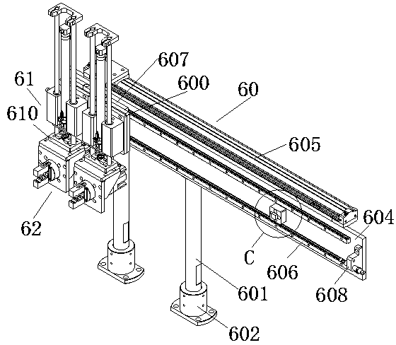
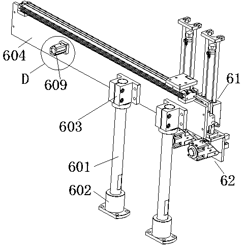
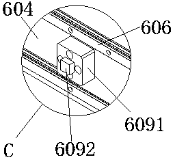
[0017] see Figure 1 to Figure 7 , the embodiment of the present invention includes:

[0018] A rotor shaft transplanting and inserting mechanism for an automatic motor rotor assembly machine. The rotor shaft transplanting and inserting mechanism for an automatic motor rotor assembly machine includes a rotary manipulator left and right moving mechanism 60, a rotary manipulator lifting device 61, and a rotary manipulator 62. Two rotary manipulators 62 are respectively installed on the lifting flange plate 610 of the two rotary manipulator lifting devices 61, and the two rotary manipulator lifting devices 61 are fixed on the left and right moving flat plat...


PUM


Abstract

The invention discloses a rotor spindle transplant and inserting mechanism of an automatic motor rotor assembly machine. The rotor spindle transplant and inserting mechanism of the automatic motor rotor assembly machine comprises a rotating mechanical arm left-right moving mechanism, rotating mechanical arm lifting devices and rotating mechanical arms. The two rotating mechanical arms are arranged on lifting flange plates of the two rotating mechanical arm lifting devices respectively. The two rotating mechanical arm lifting devices are fixed to a left-right moving flat plate of the rotating mechanical arm left-right moving mechanism. The rotating mechanical arm left-right moving mechanism is fixed to a workbench face. The rotating mechanical arms directly face an automatic rotor spindle feeding bin. By means of the mode, the rotor spindle transplant and inserting mechanism can replace manual automatic assembly at the high temperature, a machine body is provided with refrigeration circulating water which can be used repeatedly, and the rotor spindle transplant and inserting mechanism of the automatic motor rotor assembly machine is high in assembly accuracy and production efficiency, capable of better grabbing rotating spindles and capable of conducting reversing and inserting.

Description

technical field [0001] The invention relates to the field of automatic machinery, in particular to a rotor shaft transplanting and inserting mechanism of an automatic motor rotor assembly machine. Background technique [0002] There are many types of motors, which are divided into many specifications according to the occasions used and the size of the power. Motors are also widely used in automobiles, including automobile starters and glass lift motors for electric windows. The motor rotor in the motor body is a key component, and the rotor copper wire is wound on it. The rotor has two important parts. , one is the rotor shaft, and the other is the rotor winding frame wound with copper wires. These two parts are assembled through interference fit. The previous assembly process was not good. Over time, it will directly lead to gaps and instability between the two. Moreover, the production efficiency is not high, and the concentricity is poor. There is a new assembly process,...

Claims


Application Information

Patent Timeline
IPC IPC(8): H02K15/02
Inventor 施建兰
Owner 江苏九久电机有限公司
Features
  • R&D
  • Intellectual Property
  • Life Sciences
  • Materials
  • Tech Scout
  • Unparalleled Data Quality
  • Higher Quality Content
  • 60% Fewer Hallucinations
Learn More